Download
1 / 6
60 likes | 64 Vues
Renewable energy generation is quickly rising in the power sector industry and extensively used for two groups grid connected and standalone system. This paper gives the insights about fuel cell process and application of many power electronics systems. The fuel cell voltage drops bit by bit with increase in current because of losses related with fuel cell. It is difficult to control large rated fuel cell based power system without regulating tool. The issue associated with fuel based structural planning and the arrangements are extensively examined for all sorts of applications. In order to increase the reliability of fuel cell based power system, the combination of energy storage system and advanced research methods are focused in this paper. The control algorithms of power architecture for the couple of well known applications are discussed. Rameez Hassan Pala "Fuel Cell System and Their Technologies: A Review" Published in International Journal of Trend in Scientific Research and Development (ijtsrd), ISSN: 2456-6470, Volume-3 | Issue-2 , February 2019, URL: https://www.ijtsrd.com/papers/ijtsrd20316.pdf Paper URL: https://www.ijtsrd.com/engineering/electrical-engineering/20316/fuel-cell-system-and-their-technologies-a-review/rameez-hassan-pala<br>

E N D
International Journal of Trend in Scientific Research and Development (IJTSRD) Volume: 3 | Issue: 2 | Jan-Feb 2019 Available Online: www.ijtsrd.com e-ISSN: 2456 - 6470 Fuel Cell System and Their Technologies: A Review Rameez Hassan Pala M.Tech Scholar, Electrical Engineering Department, Yamuna Institute of Engineering & Technology, Yamunanagar, Haryana, India ABSTRACT Renewable energy generation is quickly rising in the power sector industry and extensively used for two groups: grid connected and standalone system. This paper gives the insights about fuel cell process and application of many power electronics systems. The fuel cell voltage drops bit by bit with increase in current because of losses related with fuel cell. It is difficult to control large rated fuel cell based power system without regulating tool. The issue associated with fuel based structural planning and the arrangements are extensively examined for all sorts of applications. In order to increase the reliability of fuel cell based power system, the combination of energy storage system and advanced research methods are focused in this paper. The control algorithms of power architecture for the couple of well-known applications are discussed. KEYWORDS: Distributed generation; Renewable energy sources; Fuel cell systems; Power-conditioning units; dc/dc converters; dc/ac inverters I. INTRODUCTION The price of fossil fuel is increasing step by step because of absence of accessibility. The power system industries are restructuring to renewable energy based power generation as an alternate solution. By considering environmental factors, the fuel cell based energy generation is a most suitable renewable system than solar and wind energy system [1]. Recently, fuel cells are rapidly developed and commercially available with high, medium and low power range applications. In order to reduce the cost of fuel cell, researchers have been focused to improve the reliability and efficiency of the fuel cell based power system [2]. The analysis report shows that the fuel cell market is increasing every year [3]. The first fuel cell was accidentally invented in 1839 by Sir William Robert Grove, however, no down to earth's utilization was found for one more century [2]. General Electric Company (GE) started creating fuel cell in the 1950s and was granted the agreement for the Gemini space mission in 1962. The 1 kW Gemini energy unit framework had a platinum stacking of 35 mg Pt/cm2 and execution of 37 mA/cm2 at 0.78 V [3]. In the 1960s enhancements were made by joining Teflon in the impetus layer specifically contiguous the electrolyte, as was finished with the GE fuel cell unit at the time. Extensive upgrades were made from the mid-1970s, forward to the reception of the completely fluorinated Nafion layer. The department of energy (DOE) and national energy technology laboratory (NETL) are mainly concentrated on developing fuel cell based power plants for standalone and grid connected applications [4]. The overall commercialization of fuel cell has not yet come. The two biggest obstructions for commercialization is life time and expense [5]. The lifetime needed by a commercial fuel cell is more than 5000 working hours for light-weight vehicles and more than 40,000 working hours of stationary power with not as much as a 10% decay [6], [7]. At present, most power devices display real execution rot after around a thousand hours of operation [8], [9]. The DOE targets are to accomplish an existence time of 40,000 h by 2011 with 40% effectiveness for distributed power and 5000-h life by 2015 to 60% efficiency for transportation. Fuel cell technology has many advantages as compared with the other conventional renewable energy sources. II. TYPES AND OPERATION OF FUEL CELLS Water electrolysis to produce hydrogen and oxygen gases is a well-known established process. Basically, the principle of a water electrolyser is to convert water and DC electricity into gaseous hydrogen and oxygen, that is to say the reverse of a hydrogen fuel cell. This process was firstly demonstrated by Nicholson and Carlisle in 1800. In the 1820s Faraday clarified the principles and in 1934 he introduced the word “electrolysis”. Electrolysis was not used commercially to produce hydrogen from water until 1902 by the Oerlikon Engineering Company. During the same period, Nernst developed the high-temperature electrolyte ZrO2 with 15% Y2O3, this being the basis for solid oxide electrolysis (SOEC) and solid oxide fuel cells (SOFC). In 1951, the first commercially available high pressure electrolyser (30 bar) was presented by Lurgi. Nowadays, low temperature electrolysis technology is available with at least 13 manufactures (3 using alkaline electrolysers and 10 using polymer membranes). On the other hand, SOEC technology is still under development. This technology attracted great interest in the 1980s because of the studies curried out by Donitz and Erdle [3], where they reported the first SOEC results within the HotElly project from Dornier System GmbH using electrolyte supported tubular SOEC. In this program, single cells have been operated during long-term periods with current densities of −0.3Acm−2 and 100% Faraday efficiency at a voltage as low as 1.07V. In addition, Westinghouse Electric Corporation Development Centre contributed to the development of SOEC. They reported Area Specific Resistance (ASR) values of about 0.6 cm2 per cell in a seven-cell stack at 1003 ◦C [4]. Research in high temperature electrolysis has increased significantly in recent years, as will be described in the present review. Research and @ IJTSRD | Unique Reference Paper ID - IJTSRD20316 | Volume – 3 | Issue – 2 | Jan-Feb 2019 Page: 153
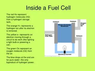
International Journal of Trend in Scientific Research and Development (IJTSRD) @ www.ijtsrd.com eISSN: 2456-6470 2.1.Types of fuel cell Fuel cells are mainly classified according to the electrolyte and types of fuel used. The main categories of fuel cells available in the market are explained below. 2.1.1.Proton Exchange Membrane Fuel Cells (PEMFC) Acid polymer is used as the electrolyte and pure hydrogen is used as fuel. The operating temperature of the PEMFC is below 100°C. Now a day, this fuel cell is popular and widely used in vehicle application. 2.1.2.Direct Methanol Fuel Cell (DMFC) In DMFC, the polymer membrane used as an electrolyte, and the fuel used is methanol. The operating temperature of DMFC is below 60 °C and it is mainly used for portable power applications below 259 W. 2.1.3.Phosphoric Acid Fuel Cell (PAFC) In PAFC, The liquid phosphoric acid is used as the electrolyte and pure hydrogen is used as the fuel. The operating temperature is around 180 °C. These types of fuel cell are particularly used as stationary power generators and which is not efficient electrically. 2.1.4.Alkaline Fuel Cell (AFC) Here, alkaline solutions are used as electrolyte of fuel cell and pure hydrogen is used as fuel. The operating temperature is about 70 °C and which is more stable. This type fuel cell is mainly used as standalone power generators. 2.1.5.Solid Oxide Fuel Cell (SOFC) This type of fuel cells is widely used as stationary power generator and its operating temperature is around 1000 °C. The solid ceramic oxide and syngas type of fuels are used in this fuel cell. 2.1.6.Molten Carbon Fuel Cell (MCFC) Here, Molten carbonate salt suspended in a porous ceramic matrix is used as the electrolyte and hydrocarbon is used as fuel. The operating temperature is around 650 °C and which is mainly used for high power application. electrolyte like zirconium Table 1 Different types of Fuel cell technology Operating Temperature potassium hydroxide (KOH) Types of fuel cell Electrolyte Fuel Oxidant Efficiency Alkaline (AFC) Direct methanol (DMFC) Phosphoric acid (PAFC) Sulfuric acid (SAFC) Proton-exchange membrane (PEMFC) pure hydrogen, or hydrazine 50–200°C O2/Air 50–55% polymer 60–200°C liquid methanol O2/Air 40–55% hydrogen from hydrocarbons and alcohol alcohol or impure hydrogen phosphoric acid 160–210°C O2/Air 40–50% sulfuric acid 80–90°C O2/Air 40–50% polymer, proton exchange membrane 50–80°C less pure hydrogen from O2/Air 40–50% molten salt such as nitrate, sulphate, carbonates ceramic as stabilised zirconia and doped perovskite thin membrane of barium cerium oxide Molten carbonate (MCFC) 630–650°C hydrocarbons or methanol CO2/O2/Air 50–60% Solid oxide (SOFC) 600–1000°C natural gas or propane O2/Air 45–60% Protonic ceramic (PCFC) 600–700°C hydrocarbons O2/Air 45–60% 2.2. Fuel cell operation The working principle of the fuel cell is simple, however, it has complicated design. Fuel cell essentially comprises of cathodes, electrolyte and fuel. The positive and negative terminals are known as cathode and anode, respectively. These are two terminals are contacted with the electrolyte inside and external electric circuit. The fuel is continuously fed to the anode while oxidant supplied to cathode. Generally, the fuel is pure hydrogen or contains some hydrogen gases like methanol, ethanol and natural gases. The oxidants are pure oxygen or contains oxygen gases like air or halogens like chlorine [20], [21], [22]. In most of the cases, the combustion of Hydrogen and oxygen produces the water and it will split into two electrochemical reactions at the electrode independently, which are termed as two cell reaction. The basic reaction taking place in a fuel cell is given in Eqs. (1), (2), (3). The overall reaction of the water electrolysis is: 1O H O H + → (1) 2 2 2 2 The reactions in the cathode and anode sides are: − + → + 2 2 ) ( 2 g H e O H 1 2 − 2 (2) O − − 2 → + (3) 2 O O e 2 III. The optimal selection of size of the fuel cell is important to locate the fuel cell in distributed system to meet the peak load demands for different applications of utilities [21]. The various intermediate ranges of different fuel cells available in markets from 0.5 kW to 2 MW are given in this classical paper [10]. Particularly the research is focusing on PEM, RECENTDEVELOPMENTINFUELCELLS @ IJTSRD | Unique Reference Paper ID - IJTSRD20316 | Volume – 3 | Issue – 2 | Jan-Feb 2019 Page: 154
International Journal of Trend in Scientific Research and Development (IJTSRD) @ www.ijtsrd.com eISSN: 2456-6470 MCFC and SOFC fuel cells, to reduce the cost of the fuel stacks and to increase their life span more than 40,000 h. At present a 7 kW capacity PEMFC development is carried out by plug power for residential applications and 250 kW capacity is under tested condition by Ballard power generation system. The Department of Energy (DOE) and Fuel Cell Energy, Inc. have researched MCFCs heavily for stationary power applications. A 1.2 MW system is largest distributed generation power plant located at Santa Clara, CA and for the commercialization purpose the development of 250, 300 and 400 kW capacity MCFC for cogeneration is researched in various countries such as Europe, Holland, Italy, Germany and Spain [5], [6], [7], [8], [9], [10], [13]. The SOFC has likewise achieved success in stationary power applications. Siemens Westinghouse has developed and tested a 250 kW hybrid system that has achieved efficiency of 52% and the efforts are also going on to develop the SOFCs in different ratings as 1 and 25 kW. They are also developing a high efficiency 5 kW SOFC-GT system to reduce its high installation cost. More over further research is focusing on PEMFC and PAFC systems for the combined heat and power generation [13], [17], [18], [19]. The research is also focusing on development of 100 kW to 1 MW DMFC and other fuel cell types such as DFAFC, DEFC, PCFC and DBFC for commercial applications [11], [12], [13], [14], [15], [16], [20]. 3.1.I–V characteristics of fuel cells The fuel cell voltage is usually very small, around 1.2 V. Due to their low output voltage it becomes necessary to stack many cells that need to be connected in cascaded series and parallel form to increase its power capacity. A typical fuel cell polarization characteristic with electrical voltage against current density is shown in Fig. 1[22]. It can be seen that a linear region exists because as the current density increases the voltage drops due to its ohmic nature. This region is called ohmic polarization, it is mainly due to internal resistance offered by various components. At low current level, the ohmic loss becomes less significant; the increase in output voltage is mainly due to activity of the chemical reactions (time taken for warm up period). So this region is also called active polarization. At very high current density the voltage fall down significantly because of the reduction of gas exchange efficiency, it is mainly due to over flooding of waters in catalyst and this region is also called concentration polarization. The performance of the fuel cell is improved by thermodynamics and electrical efficiency of the system. The thermodynamic efficiency depends upon the fuel processing, water management and temperature control of the system. But the electrical efficiency depends on the various losses over the fuel cells like ohmic loss, activation loss and concentration loss. In reality, the fuel cells differ in terms of characteristics, material used in construction and their suitability of applications. This includes military, space, portable devices, residential, stationary and transportation applications [5], [13]. IV. POWER-CONDITIONINGUNITS(PCUS) Looking to the drooping characteristics of fuel cell the development of power-conditioning units (PCUs) plays an important role to interface the fuel cell system with standalone/grid-connected system. The available fuel cell in the market is only in the range of 25–50 V due to its higher production cost. The generated fuel cell voltage is converted into directly ac supply by using single stage dc/ac inverter topologies or by a combination of a dc/dc converter in series with dc/ac inverter forming multistage conversion as shown in Fig. 2[35]. Fig.2. Schematics of fuel cell power electronic-conditioning systems The selection of power-conditioning unit is based on some significant factors like lower cost, higher efficiency, electrical isolation, ripple free and reliable operation. The efficiency of the power-conditioning unit depends upon the conduction and switching losses. The conduction losses can be effectively reduced by reducing the usage of components and their operating ranges. The switching losses can be reduced by soft switching techniques either by zero voltage crossing (ZVS) or zero current crossing (ZCS) techniques. The major advantages of soft switching technique over hard switching conditions are to reduce the losses over the device by about 20–30% [36]. In order to reduce the cost and to increase their reliability the selection of topology must have reduced component count. More over an electrical isolation is required to protect the fuel cell stacks under overload conditions. With the ideologies of fuel cell requirements and operations, several dc/dc converters and dc/ac inverter topologies are researched [35], [36], [37], [38], [39], [40], [41], [42], [43], [4 4], [45], [46], [47], [48], [49], [50], [51]. In dc/dc converters Fig.1. Typical fuel cell polarization curve @ IJTSRD | Unique Reference Paper ID - IJTSRD20316 | Volume – 3 | Issue – 2 | Jan-Feb 2019 Page: 155
International Journal of Trend in Scientific Research and Development (IJTSRD) @ www.ijtsrd.com eISSN: 2456-6470 the efficiency of the conventional boost converter is always greater than the other converter topologies like push pull, half bridge, full bridge, etc., because it has reduced component counts and simplicity in control. But for the protection point of view electrical isolation is not possible in boost converter as shown in Fig. 3. However for isolation and high boost ratio, push pull, half bridge and full bride can be considered as candidate topologies [37]. Fig. 4 shows a push pull converter is used to reduce the conduction loss in switches by operating only one switch at any time to interface the fuel cell voltage to dc bus. But the major problem is the transformer saturation which results in converter failure because the two half portions of the center tap transformer windings cannot be equal or symmetrically wound. Therefore it is suitable for low and medium power applications only [38]. Though the half bride converter as shown in Fig. 4 is suitable for high power applications, it requires large value of secondary/primary transformation ratio to deliver the desired output voltage or it requires large value of dc link capacitors to eliminate the transformer saturation that increases cost of the converter [36]. The full bridge converter as shown in Fig. 5 is suitable for high power applications compared to half bridge. Though it has more components, it has an advantage of reduced device current ratings, transformer turns ratio and the voltage and current stresses are small compared with other topologies [40], [41]. Fig.6. Isolated full bridge dc/dc converter. Development of dc/ac inverters topologies are also studied based on their relative characteristics under operating conditions. From this paper [38], [42], it is clear that for single phase loads single phase 3 wire inverter shown in Fig. 7 is the best choice compared to single bus inverter with two paralleled half bridge inverter and dual bus inverter with two split half bridge topologies, because it satisfies the ultimate basic requirements of reduced components, simple design and control. Fig.7. Single bus inverter with two paralleled half bride topology. V. Fuel cells are used in many applications including distributed generation (DG), automotive application telecommunication application. In all these applications, the technical, economic and environmental advantages of fuel cells are exploited. Some of the specific applications of fuel cell are explained in the next subsections. A.Fuel cell vehicle Fuel cells are a promising innovation in transportation. The main objective of the automotive industry is to improve the fossil fuel efficiency and reduce the harmful gas emission. Because of this fact, the growth of fuel cell rapidly increases in e-vehicles applications [24]. A fuel cell vehicle is becoming popular and attracts more due to the absence of internal combustion engines. Also, it has the advantages of simple construction with more reliable and pollution free. The main challenge of fuel cell based vehicle is to convert and control of the electrical power to mechanical power. Fig. 3 shows the fuel cells are becoming more attractive in the automotive industry. The main challenge in using fuel cell for vehicle application is to convert the power generated to mechanical power and controlling of the generated electric power. Fig. 3shows the generalized block diagram of a heavy duty fuel cell powered transit bus [25]. B.Telecommunication Fuel cells are popular in telecommunication systems [31], [32]. The fuel cell framework is currently under test by the distinctive telecom organization in worldwide for backup application. Giuseppe Gianolo et al. have been proposed a new system named electro7 fuel cell power system for telecommunication application [33]. FUEL CELL APPLICATIONS and Fig.3. Non-isolated dc/dc boost converter. Fig.4. Push pull converter. Fig.5. Isolated half bridge dc/dc converter. @ IJTSRD | Unique Reference Paper ID - IJTSRD20316 | Volume – 3 | Issue – 2 | Jan-Feb 2019 Page: 156
International Journal of Trend in Scientific Research and Development (IJTSRD) @ www.ijtsrd.com eISSN: 2456-6470 C.Underwater vehicle Recently, the fuel cells are used in submarines and ships. In ships, the fuel cells can be used as an advanced electric ship demonstrator (AESD). However, the space occupied by a fuel cell system is large and it has to be taken care. Due to higher environment temperature caused by fuel cells, the special consideration needs to be provided for other sensitive major components and ship's crew. The choice of fuel cell must be able to withstand the under level temperature and humidity of ship fuel, however, such a fuel cells are industrially accessible [34]. PEMFC is appropriate for maritime applications in light of its low working temperature, quick switch-on/switch-off conduct, and long service life. PEMFC module could be incorporated into the Advanced Electric Ship Demonstrator. The combination of the energy unit modules into AESD obliges a strong force moulding framework [35]. VI. CONCLUSIONS This paper presents a detailed review of the fuel cell, which includes the chemical and electrical aspects of the fuel cell. Moreover, the working principles of the fuel cells and the different types of fuel cells available in the market have been reported. The investigation has been made against different applications of the fuel cells. The current and research challenges in the fuel cells and its solutions are addressed with reference of the recent articles. Different typologies of the power electronic converters that can be used for fuel cell applications are discussed. The issues of standalone and grid connected fuel cell based power system are mentioned. The literature review clears that the fuel cells are used in many applications which includes Electric vehicles, power generation and in space ships, etc. As addressed the research challenges in this paper are to be incorporated for better utilization of the fuel cell technology efficiently. In addition, it is identified that the low voltage output is the main drawback of fuel cell in electrical application and in order to mitigate this issue a higher gain and efficient power electronic converters has to be developed. Furthermore, it is evident that by the year of 2030, the fuel cell replaces the conventional internal combustion engines in all commercial vehicles. REFERENCES [1]G The fuel cell industry review. E4tech strateginv thinking in sustainable energy Hirschenhofer John H. Fuel cell status, 1994. Aerosp Electron Syst Mag, IEE1994; 9(11):10–5. [6]Schmittinger Wolfgang, Vahidi Ardalan. A review of the main parameters influencing long-term performance and durability of PEM fuel cells. J Power Sources 2008; 180(1):1–14. [7]Borup Rod, et al. Scientific aspects of polymer electrolyte fuel cell durability and degradation. Chem Rev 2007; 107(10):3904–51. [8]Inaba Minoru, Schmidt Thomas J. Polymer electrolyte fuel cell durability. New York: Springer; 2009. [9]Mekhilef S, Saidur R, Safari A. Comparative study of different fuel cell technologies. Renew Sustain Energy Rev 2012; 16(1):981–9. [10]Stambouli A, Boudghene, Traversa E. Fuel cells, an alternative to standard sources of energy. Renew Sustain Energy Rev 2002;6(3):295–304. [11]Afif Ahmed, et al. Ammonia-fed fuel cells: a comprehensive review. Renew Sustain Energy Rev 2016; 60:822–35. [12]Mayer Thomas, et al. Feasibility study of 2020 target costs for PEM fuel cells and lithium-ion batteries: a two- factor experience curve approach. Int J Hydrog Energy 2012; 37(19):14463–74. [13]Sharaf Omar Z, Mehmet F Orhan. An overview of fuel cell technology: fundamentals and applications. Renew Sustain Energy Rev 2014; 32:810 53. [14]Silveira José L, Gomes LA. Fuel cell cogeneration system: a case of techno economic analysis. Renew Sustain Energy Rev 1999;3(2):233–42. [15]Choudhury Arnab, Chandra H, Arora A. Application of solid oxide fuel cell technology for power generation—a review. Renew Sustain Energy Rev 2013; 20:430–42. [16]Kirubakaran A, Shailendra Jain, Nema RK. A review on fuel cell technologies and power electronic interface. Renew Sustain Energy Rev 2009; 13.9:2430 –40. [17]Sulaiman N, et al. A review on energy management system for fuel cell hybrid electric vehicle: issues and challenges. Renew Sustain Energy Rev 2015; 52:802–14. [18]Hatti Mustapha, Meharrar A, Tioursi M. Power management strategy in the alternative energy photovoltaic/PEM fuel cell hybrid system. Renew Sustain Energy Rev 2011; 15(9):5104-10. [19]Carrette L, Friedrich KA, Stimming U1. Fuel cells- fundamentals and applications. Fuel Cells 2001;1(1):5– 39. [2]Wang Yun, et al. A review of polymer electrolyte membrane fuel cells: technology, applications, and needs on fundamental research. Appl Energy 2011; 88(4):981–1007. [20]Laughton MIA. Fuel cells. Eng Sci Educ J 2002 [22] Marshall J, Kazerani M. Design of an efficient fuel cell vehicle drivetrain, featuring a novel boost converter. Industrial Electronics Society, 2005. IECON 2005. In: Proceedings of the 31st Annual Conference of IEEE. IEEE; 2005. [3]Wand George. Fuel cells history, part 1, 14. Johnson Matthey plc; 2006 [4]Satyapal Sunita, et al. The US Department of Energy's National Hydrogen Storage Project: progress towards meeting hydrogen-powered vehicle requirements. Catal Today 2007; 120(3):246–56. [21]Emadi Ali, et al. Topological overview of hybrid electric and fuel cell vehicular power system architectures and configurations. IEEE Trans Veh Technol 2005; 54(3):763-70. [5]Wu Jinfeng, et al. A review of PEM fuel cell durability: degradation mechanisms and mitigation strategies. J Power Sources 2008; 184(1):104–19. [22]Njoya SM, Tremblay Olivier. Louis-A Dessaint. A generic fuel cell model for the simulation of fuel cell vehicles. @ IJTSRD | Unique Reference Paper ID - IJTSRD20316 | Volume – 3 | Issue – 2 | Jan-Feb 2019 Page: 157
International Journal of Trend in Scientific Research and Development (IJTSRD) @ www.ijtsrd.com eISSN: 2456-6470 Vehicle power and propulsion conference, 2009. VPPC'09. IEEE. IEEE; 2009. renewable energy resources,” Int. J. Energy Res., no. October, pp. 1–40, Nov. 2018. [23]Zhi-ling Jiang, et al. Energy management for a fuel cell hybrid vehicle. In: Proceedings of the 2010 Asia-Pacifc Power and Energy Engineering Conference (APPEEC). IEEE; 2010. [37]Venturi M, Mohrdieck C, Friedrich J. Mercedes-Benz b- class fuel cell: the world largest hydrogen vehicle fuel cell fleet experience. In: Proceedings of Electric Vehicle Symposium and Exhibition (EVS27), 2013 World. IEEE; 2013 [24]Director National Fuel Cell Research Center, University of California Irvine, CA 92697-3550gss@nfcrc.uci.edu /http://www.nfcrc.uci.edu [38]Ahn Byung Ki, Tae Won Lim. Fuel cell vehicle development at Hyundai-Kia Motors. In: Proceedings of the 1st international forum on strategic technology, IEEE; 2006 [25]Laosiripojana N, Wiyaratn W, Kiatkittipong W, Soottitantawat A, Assabumrungrat S. “Reviews on solid oxide fuel cell technology”. Engineering Journal 2009;13(1): 1–19 [39]Aso Shinji, Kizaki Mikio, Nonobe Yasuhiro. Development of fuel cell hybrid vehicles in Toyota. in: Proceedings of PCC'07 power conversion conference-Nagoya, 2007. IEEE; 2007. [26]W. Donitz, E. Erdle, Int. J. Hydrogen Energy 10 (1985) 291–295. [40]Wu Xian, Li Haibin. The reliability work in fuel cell vehicle’s road test. In: Proceedings of IEEE international conference on vehicular electronics and safety, 2006. ICVES 2006. IEEE; 2006. [27]A.O. Isenberg, Solid State Ionics 3–4 (1981) 431–437. [28]W. Donitz, R. Streicher, Chem. Ing. Tech. 52 (1980) 436– 438. [41]Romer Richard. Fuel cell systems provide clean backup power in telecom applications worldwide. In: Proceedings of 2011 IEEE 33rd international tele- communications energy conference (INTELEC), Ieee; 2011. [29]Larminie James, Dicks Andrew. Fuel cell explained. 2nd ed. Wiley Inc.; 2003. [30]Nguyen QM. Ceramic Fuel Cells. J. Am. Ceram. Soc. 1993;76(3):563–88. [31]Brawn R. Report from the Solar Energy Laboratory. University of Wisconsin-Madison, WI. February 2015 (http://sel@sel.me.wisc.edu/). [42]Xia Lei, Jeff Bentley. Fuel cell power systems for telecommunications; 2001. p. 677–82 [43]Gianolio Giuseppe. et al. Fuel cell based power system for backup applications: Telecom Italia and otherfield test results. In: Proceedings of 29th international telecommunications energy conference, 2007. INTELEC 2007. IEEE; 2007. [32]Mc Evoy A. J. Laboratoire de Photonique et des Interfaces. Ecole Polytechnique Fe´derale de Lausanne, Fuel cell technology status and prospects. June 1998. [33]O. Krishan and Sathans, “Design and Techno-Economic Analysis of a HRES in a Rural Village,” Procedia Comput. Sci., 6th International Conference on Smart Computing and Communications, ICSCC 2017, 7-8 December 2017, Kurukshetra, India vol. 125, pp. 321–328, 2018. [44]Shih Nai-Chien, et al. Development of a small fuel cell underwater vehicle. 2013;38(25):11138-43. Int J Hydrog Energy [45]Luckose L, Hess HL, Johnson BK. Power conditioning system for fuel cells for integration to ships. In: Proceedings of vehicle power and propulsion conference, 2009. VPPC'09. IEEE. IEEE; 2009. [34]O. Krishan and Sathans, “Frequency regulation in a standalone wind-diesel hybrid power system using pitch-angle controller,” in Proceedings of the 10th INDIACom; 2016 3rd International Conference on Computing for Sustainable Global Development, INDIACom 2016, 2016. [46]Mann Ronald F, et al. Development and application of a generalised steady-state electrochemical model for a PEM fuel cell. J Power Sources 2000;86(1):173-80 [35]O. Krishan and Sathans, “Optimum sizing and economical assessment of grid integrated hybrid system for a rural village: A case study,” in 1st IEEE International Conference on Power Electronics, Intelligent Control and Energy Systems, ICPEICES 2016, 2017. [47]Xue XD, Cheng KWE, Sutanto Danny. Unified mathematical modelling of steady-state and dynamic voltage-current characteristics for PEM fuel cells. Electrochim Acta 2006; 52(3):1135-44. [48]Rowe Andrew, Li Xianguo. Mathematical modeling of proton exchange membrane fuel cells. J Power Sources 2001; 102(1):82-96. [36]O. Krishan and S. Suhag, “An updated review of energy storage systems: Classification and applications in distributed generation power systems incorporating @ IJTSRD | Unique Reference Paper ID - IJTSRD20316 | Volume – 3 | Issue – 2 | Jan-Feb 2019 Page: 158