Download
1 / 5
50 likes | 54 Vues
Temperature controlling is one of the most important process variables in the process control. In this paper describes the design and implementation of a Wireless Sensor Networks WSN based on XBee technology to monitor the history and current temperature information of remote locations. In this work, the microcontroller is used to compute and compare the value of current temperature and the set point values. LCD is used to display the result data. This result data is also sent to the microcontroller where the operator controls the whole process. Then, the signal passes to the relays to On Off case of the fan for maintaining the correct temperature. Mon Mon Aye | Aye Myat Myat Myo | Zar Chi Soe "Microcontroller Based Temperature Monitoring and Controlling System using XBee Network" Published in International Journal of Trend in Scientific Research and Development (ijtsrd), ISSN: 2456-6470, Volume-3 | Issue-5 , August 2019, URL: https://www.ijtsrd.com/papers/ijtsrd27842.pdf Paper URL: https://www.ijtsrd.com/engineering/electronics-and-communication-engineering/27842/microcontroller-based-temperature-monitoring-and-controlling-system-using-xbee-network/mon-mon-aye<br>

E N D
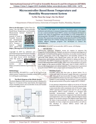
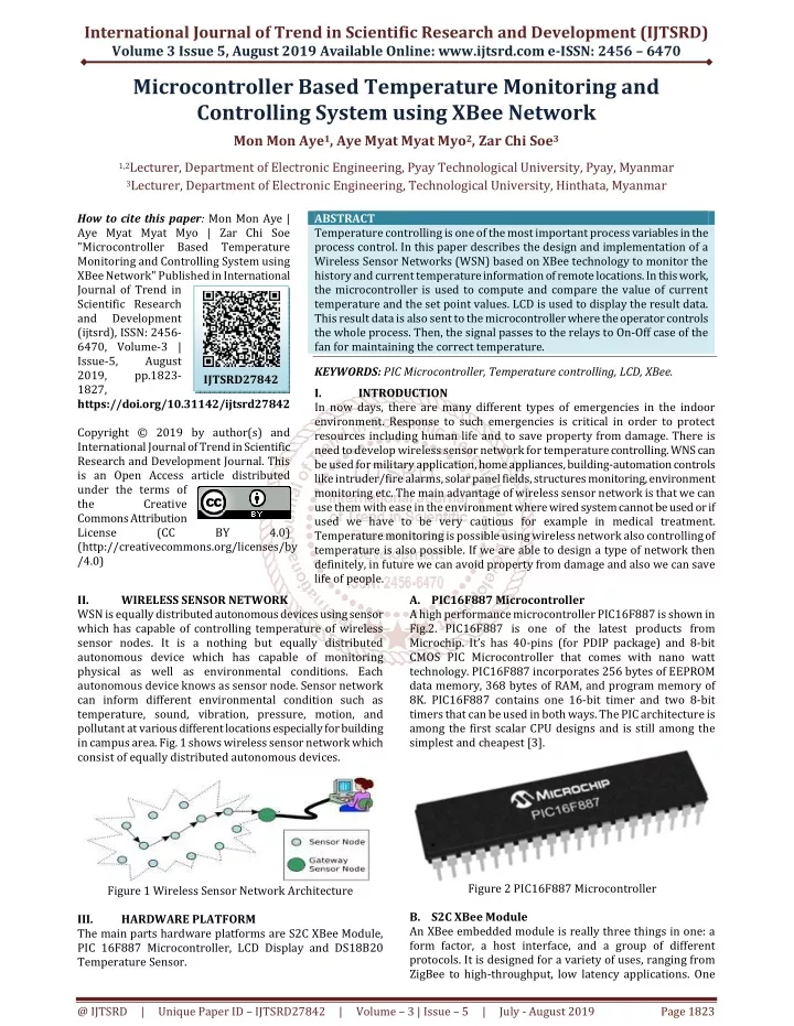
International Journal of Trend in Scientific Research and Development (IJTSRD) Volume 3 Issue 5, August 2019 Available Online: www.ijtsrd.com e-ISSN: 2456 – 6470 Microcontroller Based Temperature Monitoring and Controlling System using XBee Network Mon Mon Aye1, Aye Myat Myat Myo2, Zar Chi Soe3 1,2Lecturer, Department of Electronic Engineering, Pyay Technological University, Pyay, Myanmar 3Lecturer, Department of Electronic Engineering, Technological University, Hinthata, Myanmar How to cite this paper: Mon Mon Aye | Aye Myat Myat Myo | Zar Chi Soe "Microcontroller Based Temperature Monitoring and Controlling System using XBee Network" Published in International Journal of Trend in Scientific Research and Development (ijtsrd), ISSN: 2456- 6470, Volume-3 | Issue-5, August 2019, pp.1823- 1827, https://doi.org/10.31142/ijtsrd27842 Copyright © 2019 by author(s) and International Journal of Trend in Scientific Research and Development Journal. This is an Open Access article distributed under the terms of the Creative Commons Attribution License (CC (http://creativecommons.org/licenses/by /4.0) II. WIRELESS SENSOR NETWORK WSN is equally distributed autonomous devices using sensor which has capable of controlling temperature of wireless sensor nodes. It is a nothing but equally distributed autonomous device which has capable of monitoring physical as well as environmental conditions. Each autonomous device knows as sensor node. Sensor network can inform different environmental condition such as temperature, sound, vibration, pressure, motion, and pollutant at various different locations especially for building in campus area. Fig. 1 shows wireless sensor network which consist of equally distributed autonomous devices. ABSTRACT Temperature controlling is one of the most important process variables in the process control. In this paper describes the design and implementation of a Wireless Sensor Networks (WSN) based on XBee technology to monitor the history and current temperature information of remote locations. In this work, the microcontroller is used to compute and compare the value of current temperature and the set point values. LCD is used to display the result data. This result data is also sent to the microcontroller where the operator controls the whole process. Then, the signal passes to the relays to On-Off case of the fan for maintaining the correct temperature. KEYWORDS: PIC Microcontroller, Temperature controlling, LCD, XBee. I. INTRODUCTION In now days, there are many different types of emergencies in the indoor environment. Response to such emergencies is critical in order to protect resources including human life and to save property from damage. There is need to develop wireless sensor network for temperature controlling. WNS can be used for military application, home appliances, building-automation controls like intruder/fire alarms, solar panel fields, structures monitoring, environment monitoring etc. The main advantage of wireless sensor network is that we can use them with ease in the environment where wired system cannot be used or if used we have to be very cautious for example in medical treatment. Temperature monitoring is possible using wireless network also controlling of temperature is also possible. If we are able to design a type of network then definitely, in future we can avoid property from damage and also we can save life of people. A.PIC16F887 Microcontroller A high performance microcontroller PIC16F887 is shown in Fig.2. PIC16F887 is one of the latest products from Microchip. It’s has 40-pins (for PDIP package) and 8-bit CMOS PIC Microcontroller that comes with nano watt technology. PIC16F887 incorporates 256 bytes of EEPROM data memory, 368 bytes of RAM, and program memory of 8K. PIC16F887 contains one 16-bit timer and two 8-bit timers that can be used in both ways. The PIC architecture is among the first scalar CPU designs and is still among the simplest and cheapest [3]. IJTSRD27842 BY 4.0) Figure 2 PIC16F887 Microcontroller Figure 1 Wireless Sensor Network Architecture B.S2C XBee Module An XBee embedded module is really three things in one: a form factor, a host interface, and a group of different protocols. It is designed for a variety of uses, ranging from ZigBee to high-throughput, low latency applications. One III. The main parts hardware platforms are S2C XBee Module, PIC 16F887 Microcontroller, LCD Display and DS18B20 Temperature Sensor. HARDWARE PLATFORM @ IJTSRD | Unique Paper ID – IJTSRD27842 | Volume – 3 | Issue – 5 | July - August 2019 Page 1823
International Journal of Trend in Scientific Research and Development (IJTSRD) @ www.ijtsrd.com eISSN: 2456-6470 nice thing about Xbee is it can do anything that ZigBee can do (if you use the ZigBee version), but it also includes other protocol stacks in the same form factor and host interface. The form factor deals with a common shape and pin configuration in the hardware. It has a 20-pin or 37-pin socket (depending on the hardware footprint you select), which takes up a very small amount of space on the circuit board. This configuration makes it easier for you to bring a new device into the market, because if the form factor is the same, the host interface is the same [1]. Unlike ZigBee, DigiMesh has only one node type. All nodes can route data and are interchangeable. Fig. 3 is S2C XBee Module. Figure 5 LCD Display E.Interfacing Relay with PIC Microcontroller In this system, to ON/OFF fan or heater, relay is used. A relay is an electromagnetic switch which is used to switch High Voltage/Current using low power circuit. Relay are used where it is necessary to control a circuit by a separate low- power signal, or where several circuits must be controlled one signal [4]. Fig. 6 shows Relay Design Circuit. Figure 6 Circuit Design of Relay Figure 3 S2C XBee Module F.X-CTUSOFTWARE XCTU is a free multi-platform application that enables developers to manage Digi radio frequency (RF) modules through a simple-to-use graphical interface. The application includes embedded tools that make it easy to set up, configure, and test Digi RF modules. To use XBee module in this system, we must configure this XBee, first. XCTU software is most reliable to configure this XBee module [6]. Fig. 7 shows the XCTU Software. C.DS18B20 Temperature Sensor Fig. 4 shows DS18B20 temperature sensors. The DS18B20 is a small temperature sensor with a built in 12bit ADC. It can be easily connected to an Arduino digital input. The sensor communicates over a one-wire bus and requires little in the way of additional components. It requires only the data pin connected to the microcontroller with a pull up resistor and the other two pins are used for power. The temperature valuemeasured by thesensor will be stored in a 2-byte register inside the sensor. This data can be read by the using the 1- wire method by sending in a sequence of data. DS18B20 has a unique 64-bit serial code, which allows multiple DS18B20s to function on the same 1-Wire bus. The DS18B20 has an operating temperature range of -55°C to +125°C and the accuracy is ±0.5°C over the range of -10°C to +85°C [7]. Figure 7. XCTU Software IV. The implementation of the proposed XBee wireless sensor network includes: End Node and Base Station hardware and software Implementation. A.Base Station (Master Control) Implementation Fig. 8 shows the block diagram of Base Station. In this station, the user needs to define the desired value of temperature by using the setting key. And then the base station has been implemented to collect end nodes sensor information and display this information on LCD. The MCU has been the main controller of base station operation. The MCU receives the end nodes sensors information from the Coordinator XBee module. The XBee module has been connected to MCU through UART1 interface. SYSTEM IMPLEMENTATION Figure 4 DS18B20 Digital Temperature Sensor D.Liquid Crystal Display (LCD) A 2x16 LCD (1602A) is shown in Fig. 5 with 4-bit interface mode has been chosen to display the sensor readings received from end nodes. @ IJTSRD | Unique Paper ID – IJTSRD27842 | Volume – 3 | Issue – 5 | July - August 2019 Page 1824
International Journal of Trend in Scientific Research and Development (IJTSRD) @ www.ijtsrd.com eISSN: 2456-6470 temperature is not greater than, the heater relay will ON and fan will OFF. In this stage, the LCD will display new temperature data and end-device will send that data to microcontroller. Finally, the microcontroller sets this new temperature and keeps this condition until the new conditions appear. Figure 8 Block Diagram of Base Station B.End Node (Slave Controller) Implementation Fig. 9 shows the structure of proposed XBee end node. End node has the sensor that senses the environmental information and sends microcontroller which processes the information and displays the data on LCD. Then the processed information has been sent to the XBee module. The XBee module sends the information to the coordinator. this information to the Figure 10 Flow Chart of Master Control Fig. 10 and Fig. 11 show the flowcharts for Base Station and End Nodes operation. Fig. 12 and Fig. 13 show selections of End-device module and coordinator module. Fig. 14 the final Xbee coordinator and end-device System hardware design. Figure 9 Block Diagram of Slave Controller The XBee has been connected to PIC16F887 through UART interface. And then, the desire data will be resend from coordinator XBee to slave and the PIC controls the system to ON or OFF fan or heater. If the real temperature is higher than the desire temperature from setting key, the fan will ON and if not the fan will OFF. As a power source, each end node has been provided by DC power using 9V battery and because that MCU works on DC 5V and XBee module works on DC 3.3V, voltage regulators has been used. V. SYSTEM OPERATION The system operation initializes from base station. The base station sends a request to end node. In this station, the user can choose increment or decrement of the temperature. After pressing the setting key, the changed temperature will display on LCD and send to microcontroller. If an end node receives the request, this node will get the information from temperature sensor and upload it to the slave XBee module. The XBee module sends this information to the base station coordinator. Once the microcontroller of base station gets the end nodes information from the XBee module through UART interface, the MCU processes the information received from end node and sends that information to the LCD module. The LCD will display the received sensor readings. The data that end-device received is real temperature. When real temperature is greater than the desire temperature, the fan will ON and heater relay will OFF. The desire temperature is changed by other side, coordinator. If the real Figure 11 Flow Chart of Slave Control @ IJTSRD | Unique Paper ID – IJTSRD27842 | Volume – 3 | Issue – 5 | July - August 2019 Page 1825
International Journal of Trend in Scientific Research and Development (IJTSRD) @ www.ijtsrd.com eISSN: 2456-6470 Figure 12 Selected End-device Module Figure 16 Sensor Senses the Real Room Temperature and Shows on LCD Figure 13 Selected Coordinator Modules Figure 17 Fan Turns On When the sensor is getting heat, the ambient temperature may be unstable that is it can rise the room temperature and sends data to the coordinator. Now, real temperature is higher than the desire data, fan will turn on. This is shown in Fig 17. On the testing, the desired temperature value would be increased to 30˙C in coordinator section. Fig. 18 shows that the setting key adjusted to new temperature. Figure 14 Final Xbee Coordinator and End-device System Hardware Design VI. When the user wants to change the room temperature, the setting key is used for changing. Fig. 15 shows the temperature adjusting by Setting Key in Coordinator section. Fig. 16 shows the real room temperature from the sensor and shows on LCD. TESTANDRESULTS Figure 18 Setting Key adjusted to new temperature When the new set value can be sensed on the end device, the setting key change the temperature that is higher than the actual room temperature, the fun will turn OFF as shown in Fig. 19. Figure 15 Temperature Adjust by Setting Key in Coordinator @ IJTSRD | Unique Paper ID – IJTSRD27842 | Volume – 3 | Issue – 5 | July - August 2019 Page 1826
International Journal of Trend in Scientific Research and Development (IJTSRD) @ www.ijtsrd.com eISSN: 2456-6470 ACKNOWLEDGEMENT I would wish to acknowledge the many colleagues at Pyay Technological University who have contributed to the passing this research paper. REFERENCES [1]https://www.link-labs.com/blog/zigbee-vs-xbee [2]Stefan Posland, Ubiquitous Computing: Smart Devices, Environments and Interactions, Wiley, 2009 [3]https://www.eleprocus.com/pic-microcontroller [4]Wireless http://www.sensornetworks.org Sensor Network Research Group, [5]Arduino, http://arduino.cc/. Figure 19 Fan Turns OFF [6]Introduction https://www.digi.com/products/xbee-rf- solutions/xctu- software/xctu to XCTU Software VII. In this paper, a prototype of an embedded wireless sensor network has been built based on PIC microcontrollers and XBee module. The environmental temperature monitoring has been considered in this system to demonstrate the capability of applying the system. The system has the character of wireless on wiring to remove the limitation of traditional wired network system for any kind of remote conditions monitoring. Wireless technology has already become an important application which usually integrated to a wide range of device and other technologies. This system uses the XBee as the wireless module. The combination of low-cost hardware, very good radio performance makes XBee a competitive choice on the wireless market. CONCLUSION [7]W. Dargie, C. Poellabauer, and Wiley Inter Science (Online service), Fundamentals of wireless sensor networks theory and practice. Chichester, West Sussex, U.K.; Hoboken, NJ: Wiley, 2010. [8]Digi International Inc, XBee ZNet2.5/XBee-PRO ZNet2.5 OEM RF Modules, Product Manual v1.x.4x - ZigBee Protocol For OEM RF Module Part Numbers: XB24- BxIT-00x,Digi International Inc.11001 Bren Road East Minnetonka, MN 55343877 912-3444 or 952 912-3444 http://www.digi.com @ IJTSRD | Unique Paper ID – IJTSRD27842 | Volume – 3 | Issue – 5 | July - August 2019 Page 1827