Download
1 / 7
80 likes | 151 Vues
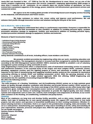
In the recent year, robots are turned out to be an ingredient over which many people had shown there interest. Robotics has gained popularity due to the advancement of many technologies of computing and nano technologies. So, we proposed to design something that can make humans life easier and comfortable. This project, which is our endeavor to design a tire fighting robot. Comprises of a machine which not only has the basic features of the robot, but also has the ability to detect re and extinguish it. The need of the hour is make a device which can detect tire, even if it is small and take the necessary action to put it off. Many house hold item catch re when someone is either sleeping or away and that lead many hazardous conditions in the re is not putted off in time. So, be work as an electronics engineer is to design and built system that can automatically detect and extinguish fire. This advanced project allows a user to control a fire fighter robot equipped with water tank and gun remotely wirelessly for extinguishing fires. For this purposes the system uses an RF remote for remote operation along with RF receiver based microcontroller Circuit for operating the Robot and water pump. The RF based remote transfer's user's commands through RF signals which are received by the receiver circuit. The receiver circuit now decodes the data commands sent. It then forwards to the microcontroller. Now the microcontroller processes these instruction and then instructions the motors to run the robot in desired direction. It also operates the solenoid valve to spray water based on user's commands. This allows the user to operate the robot and put off the fire by standing at a safe distance. V. Mangayarkarasi "Remote Controlled Fire Fighting Robot" Published in International Journal of Trend in Scientific Research and Development (ijtsrd), ISSN: 2456-6470, Volume-2 | Issue-5 , August 2018, URL: https://www.ijtsrd.com/papers/ijtsrd15936.pdf Paper URL: http://www.ijtsrd.com/engineering/electronics-and-communication-engineering/15936/remote-controlled-fire-fighting-robot/v-mangayarkarasi<br>

E N D
International Research Research and Development (IJTSRD) International Open Access Journal Remote Controlled Fire Fighting Robot V. Mangayarkarasi Senior Grade, Department of Electronics Communication Engineering, Nachimuthu Polytechnic College, Pollachi, Tamil Nadu, India I. INTRODUCTION The project is designed to develop a fire fighting robot using RF technology for remote operation. The robotic vehicle is loaded with water tanker and a pump which communication to throw water. An ATMEGA series of microcontroller is used for the desired operation. At the transmitting end using push buttons, commands are sent to the receiver to control the movement of the robot either to move forward, backward and left or right etc. At the receiving end three motors are interfaced to the microcontroller where two of them are used for the movement of the vehicle and the remaining one to position the arm of the robot. The RF transmitter acts as a RF remote control that has the advantage of adequate range (u to 200 meters) with proper antenna, while the receiver decodes before feeding it to another microcontroller to drive DC motors via motor driver IC for necessary work. A water tank along with water pump is mounted on the robot body and its operation is ca out from the microcontroller output through appropriate signal from the transmitting end. The whole operation is controlled by an ATMEGA 16 series microcontroller. A motor driver IC is interfaced to the microcontroller through which the controller drives the motors. Further the project can be enhanced by interfacing it with a wireless camera so that the person controlling it can view operation of the robot remotely on a screen. 1.1 Robot A robot is a machine especially one programmable by a computer capable of carrying out a complex series of actions automatically. Robots can be guided by an external control device or the control may be embedded within. Robots may be constructed to take embedded within. Robots may be constructed to take International Journal of Trend in Scientific Scientific (IJTSRD) International Open Access Journal ISSN No: 2456 ISSN No: 2456 - 6470 | www.ijtsrd.com | Volume 6470 | www.ijtsrd.com | Volume - 2 | Issue – 5 Remote Controlled Fire Fighting Robot Remote Controlled Fire Fighting Robot Lecturer Senior Grade, Department of Electronics Communication Engineering, Nachimuthu Polytechnic College, Pollachi Senior Grade, Department of Electronics Communication Engineering, ABSTRACT In the recent year, robots are turned out to be an ingredient over which many people had shown there interest. Robotics has gained popularity due to the advancement of many technologies of computing and nano technologies. So, we proposed to design something that can make humans life easier and comfortable. This project, which is our endeavor to design a tire fighting robot. Comprises of a machine which not only has the basic features of the robot, but also has the ability to detect fire and extingui need of the hour is make a device which can detect tire, even if it is small and take the necessary action to put it off. Many house hold item catch someone is either sleeping or away and that lead many hazardous conditions in the fire is not putted off in time. So, be work as an electronics engineer is to design and built system that can automatically detect and extinguish fire. This advanced project allows a user to control a fire fighter robot equipped with water tank and gun remotely wirelessly for extinguishing fires. For this purposes the system uses an RF remote for remote operation along with RF receiver based microcontroller Circuit for operating the Robot and water pump. The RF based remote transfer’s user’s commands through RF signals which are received by the receiver circuit. The receiver circuit now decodes the data commands sent. It then forwards to the microcontroller. Now the microcontroller processes these instruction and then instructions the motors to run the robot in desired direction. It also operates the solenoid valve to spray water based on user’s commands. This allows the user to operate the robot and put off the fire by standing at a safe distance. Keywords:Fire Fighting, Micro Controller, Remote Control Robot, Sensor In the recent year, robots are turned out to be an ingredient over which many people had shown there interest. Robotics has gained popularity due to the advancement of many technologies of computing and nano technologies. So, we proposed to design something that can make humans life easier and project, which is our endeavor to design a tire fighting robot. Comprises of a machine which not only has the basic features of the robot, but The project is designed to develop a fire fighting robot using RF technology for remote operation. The robotic vehicle is loaded with water tanker and a pump which communication to throw water. An ATMEGA 16 series of microcontroller is used for the desired operation. At the transmitting end using push buttons, commands are sent to the receiver to control the movement of the robot either to move forward, backward and left or right etc. At the receiving end three motors are interfaced to the microcontroller where two of them are used for the movement of the vehicle and the remaining one to position the arm of the robot. The RF transmitter acts as a RF remote control that has the advantage of adequate range (up to 200 meters) with proper antenna, while the receiver decodes before feeding it to another microcontroller to drive DC motors via motor driver IC for necessary work. A water tank along with water pump is mounted on the robot body and its operation is carried out from the microcontroller output through appropriate signal from the transmitting end. The whole operation is controlled by an ATMEGA 16 series microcontroller. A motor driver IC is interfaced to the microcontroller through which the controller ives the motors. Further the project can be enhanced by interfacing it with a wireless camera so that the person controlling it can view operation of the robot is is controlled controlled over over wireless wireless fire and extinguish it. The need of the hour is make a device which can detect tire, even if it is small and take the necessary action to put it off. Many house hold item catch fire when someone is either sleeping or away and that lead s not putted off in time. So, be work as an electronics engineer is to design and built system that can automatically detect and extinguish fire. This advanced project allows a user to control a fire fighter robot equipped with water wirelessly for extinguishing fires. For this purposes the system uses an RF remote for remote operation along with RF receiver based microcontroller Circuit for operating the Robot and water pump. The RF based remote transfer’s user’s ignals which are received by the receiver circuit. The receiver circuit now decodes the data commands sent. It then forwards to the microcontroller. Now the microcontroller processes these instruction and then instructions the motors to sired direction. It also operates the solenoid valve to spray water based on user’s commands. This allows the user to operate the robot and put off the fire by standing at a safe distance. A robot is a machine especially one programmable by a computer capable of carrying out a complex series of actions automatically. Robots can be guided by an external control device or the control may be Fire Fighting, Micro Controller, Remote @ IJTSRD | Available Online @ www.ijtsrd.com @ IJTSRD | Available Online @ www.ijtsrd.com | Volume – 2 | Issue – 5 | Jul-Aug 2018 Aug 2018 Page: 820
International Journal of Trend in Scientific Research and Development (IJTSRD) ISSN: 2456-6470 on human form but most robots are machines designed to perform a task with no regard to how they look. In other words a robot is a machine designed to execute one or more tasks repeatedly, withspeed and precision. Robots can be autonomous or semi-autonomous and range from humanoids such as Honda's Advanced Step in Innovative Mobility (ASIMO) and TOSY's TOSY Ping Pong Playing Robot (TOPIO) to industrial robots, medical operating robots, patient assist robots, dog therapy robots, collectively programmed swarm robots, UAV drones such as General Atomics MQ-1 microscopic nano robots. By mimicking a lifelike appearance or automating movements, a robot may convey a sense of intelligence or thought of its own. Autonomous Things are expected to proliferate in the coming decade, with home robotics and the autonomous car as some of the main drivers. The branch of technology that deals with the design, construction, operation, and application of robots, as well as computer systems for their control, sensory feedback, and information processing is robotics. These technologies deal with automated machines that can take the place of humans in dangerous environments or manufacturing resemble humans in appearance, behavior, or cognition. Many of today's robots are inspired by nature contributing to the field of bio-inspired robotics. These robots have also created a newer branch of robotics: soft robotics. Robots have replaced humans in performing repetitive and dangerous tasks which humans prefer not to do, or are unable to do because of size limitations, or which take place in extreme environments such as outer space or the bottom of the sea. There are concerns about the increasing use of robots and their role in society. Robots are blamed for unemployment as they replace workers in increasing numbers of functions. The use of robots in military combat raises ethical concerns. The possibilities of robot autonomy and potential repercussions have been addressed in fiction and may be a realistic concern in the future. 1.1.1 Types of Robot Now day’s robots do a lot of different tasks in many fields and the number of jobs entrusted to robots is growing steadily. That’s why in my option one of the best way how to divide robots into a division by their application. There are, ?Industrial Robot ?Domestic Robot or Household Robot ?Medical Robot ?Service Robot ?Military Robot ?Fire Extinguish Robot 1.1.2 Fire Extinguish Robot Fire extinguishing robot reduces the risk of fire fighting. The fire sensor helps the detect fire and smoke, etc. These types of robots are very helpful for fire squad. An automatic fire extinguisher robot is a hardware based model used for extinguishing the fire automatically during fire accidents. This robot will move in a direction with respect to the fire intensity with the help of ZIGBEE communication. The robot shield is coated with some special material that is capable of withstanding very high temperature. During fire accidents this robot has to follow the black strips on a white floor and can extinguish the fire on the fired place. It takes long time for human to take action on extinguishing the fire. Even if we put fire alarms, it takes long time for the fire brigade to reach the location. By that time it can cause huge loss of properties. This robot does not require any human presence. It can start extinguishing the fire immediately so that the fire does not spread a lot and can be controlled easily. As soon as the fire starts, human fire brigade is also informed to be on the safe side. The robot finds its applications in rescue operations during the fire accidents where possibilities for service men to enter the fire prone area is very less and also during wars to perform rescue functions. The most added advantage of this robot is that it turns on automatically as it detects the fire around its surroundings by using thermocouple. 1.1.3 Feature ?The robot can move both forward and reverse direction and can turn in both left and right direction ?The movement of the robot is controlled by IR sensors. ?It can sense the fire using fire sensors. ?It accumulators a water tank and water pump to extinguishing fire. ?A 12v battery is used to drive the circuitry. Predator, and even processes, or rising technological @ IJTSRD | Available Online @ www.ijtsrd.com | Volume – 2 | Issue – 5 | Jul-Aug 2018 Page: 821
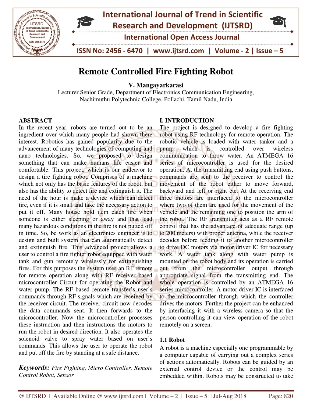
International Journal of Trend in Scientific Research and Development (IJTSRD) ISSN: 2456 in Scientific Research and Development (IJTSRD) ISSN: 2456 in Scientific Research and Development (IJTSRD) ISSN: 2456-6470 1.1.4 Application ?Chemical Industries ?Shopping malls ?Buildings ?Gas Industries ?Petrol bunk ?Cotton Industries. III. DESCRIPTION OF THE PROJECT III. DESCRIPTION OF THE PROJECT 3.1 Block Diagram of Fire Fighting Robot 3.1 Block Diagram of Fire Fighting Robot II. METHODOLOGY The project uses HT12E Encoder which converts 4 bit data to serial output which is then fed to the RF module for transmitting the same to be received by the receiver RF module the output of which is fed to HT12D the serial decoder IC, the output of which is fed to controller. The transmitting end MC is connected to a set of pushbutton. Thus while a particular button is pressed the program executed delivers corresponding4 data which are then transmitted serially at port 1. The data so received at the receiver end of port1 operates the motor through motor driver IC L293D as required being interfaced from the Microcontroller output port 2. The transmitter is powered by a 6v battery in series with a silicon diode to finally develop required voltage for microcontroller circuit. The receiver is powered by a 12v battery in series with a silicon diode to protect the circuits from accidental reverse battery connection. 5V DC out of the 12V available from regulator IC 7805 is fed to the controller, decoder, the motor driver IC L293D pin 8 for operation of the motor The receiving unit uses one more motor driver IC L293D for driving one DC Motor for arm operat with a boom mounted on its shaft. At the end of the shaft a nozzle is connected to a water tanks mounted water pump which is powered from “NO” contacts of a relay that is driven by transistor Q1 from the output of MC pin 15, thus in the event of a fire the robotic vehicle is moved over to the location by operating the left, right, forward & backward button etc. After it reaches the site the nozzle mounted takes position through the water on the fire from the water tank mounted DC pump actuated by the relay RL1. Thus the fire can be extinguished. The project uses HT12E Encoder which converts 4 bit data to serial output which is then fed to the RF module for transmitting the same to be received by receiver RF module the output of which is fed to HT12D the serial decoder IC, the output of which is The transmitting end MC is connected to a set of pushbutton. Thus while a particular button is pressed Figure 1: Block Diagram of Fire Fighting Robot Figure 1: Block Diagram of Fire Fighting Robot orresponding4- bit Block diagram consists of following, Block diagram consists of following, data which are then transmitted serially at port 1. The data so received at the receiver end of port1 operates the motor through motor driver IC L293D as required being interfaced from the Microcontroller ?Input Section ?Control Section ?Output Section is powered by a 6v battery in series with a silicon diode to finally develop required voltage for microcontroller circuit. 3.2 Input Section Input section consists ?Fire Sensor(Thermistor) ?RF Receiver(Decoder) 3.2.1 Fire Sensor (Thermistor) A thermistor is a type of resistor whose resistance varies significantly with the temperature, more so than in standard resistors. The world is a portmanteau of thermal and resistor. Thermistors are widely used as in rush current limiters, temperature sens resetting over current protectors, and self heating elements. Thermistors differ from resistance temperature detectors (RTDs) in that the material used in a thermistor is generally a ceramic or polymer, while RTDs use pure metals. The response is also different, RTDs are useful over larger temperatures ranges, while thermistors typically achieve a higher precision within a limited temperature within a limited temperature range, typically -900C to 1300C. The receiver is powered by a 12v battery in series with a silicon diode to protect the circuits from 3.2.1 Fire Sensor (Thermistor) A thermistor is a type of resistor whose resistance varies significantly with the temperature, more so than in standard resistors. The world is a portmanteau of thermal and resistor. Thermistors are widely used as in rush current limiters, temperature sensors, self- protectors, and self –regulating heating elements. Thermistors differ from resistance temperature detectors (RTDs) in that the material used in a thermistor is generally a ceramic or polymer, while RTDs use pure metals. The temperature response is also different, RTDs are useful over larger temperatures ranges, while thermistors typically achieve a higher precision within a limited temperature within a limited temperature range, 5V DC out of the 12V available from regulator IC 7805 is fed to the controller, decoder, the motor driver IC L293D pin 8 for operation of the motor. The receiving unit uses one more motor driver IC L293D for driving one DC Motor for arm operation with a boom mounted on its shaft. At the end of the shaft a nozzle is connected to a water tanks mounted water pump which is powered from “NO” contacts of a relay that is driven by transistor Q1 from the output fire the robotic vehicle is moved over to the location by operating the left, right, forward & backward button etc. After it reaches the site the nozzle mounted motor position through the water on the fire from the ed by the relay @ IJTSRD | Available Online @ www.ijtsrd.com @ IJTSRD | Available Online @ www.ijtsrd.com | Volume – 2 | Issue – 5 | Jul-Aug 2018 Aug 2018 Page: 822
International Journal of Trend in Scientific Research and Development (IJTSRD) ISSN: 2456 in Scientific Research and Development (IJTSRD) ISSN: 2456 in Scientific Research and Development (IJTSRD) ISSN: 2456-6470 Conduction Model NTC Thermistor Many NTC thermistors are made from a pressed disc, rod, and plate bead or cast chip of a semiconductor such as sintered metal oxide. They work because raising the temperature of a semiconductor increases the number of active charge carries them into the conduction band. The more charge carries that are available, the more current a material can conduct. In certain materials like ferric oxide with titanium doping a n-type semiconductor is formed and the charge carriers are electrons. In materials such as nickel oxide with lithium doping a p semiconductor is created where holes are the charge carriers. NTC thermistors can be also used to monitor the temperature of an incubator. Thermistors are also commonly used in modern digital thermostats and to monitor the temperature of battery packs while charging. 3.2.2 RF Receiver (Decoder) Transmitter, upon receiving serial data from encoder IC, transmits it wirelessly to the RF receiver. The receiver, upon receiving these signals, sends them to the decoder IC through pin2. The serial data is received at the data pin (DIN, pin 14) of HT12D. The Decoder then receives the original parallel format from the received serial data. HT12D is a decoder integrated circuit that belongs 212 series of decoders. This series of decoders are mainly used for remote control system applications, like burglar alarm, car door controller, security system etc. It is mainly provided to interface RF and infrared circuits. They are paired with 212 series of encoders. The chosen pair of encoder/decoder should have same number of addresses and data format. In simple terms, HT12D converts the serial input into parallel outputs. It decodes the serial addresses and data received by, say, an RF receiver data and sends them to output data pins. The serial input data is compared with the local addresses three times continuously. The input data code is decoded when no error or unmatched codes are found. A valid transmission in indicated by a high signal at VT pin. HT12D is capable of decoding 12 bits, of which 8 are address bits and 4 are data bits. The data on 4 bit latch type output pins remain unchanged until new is received. Many NTC thermistors are made from a pressed disc, rod, and plate bead or cast chip of a semiconductor such as sintered metal oxide. They work because raising the temperature of a semiconductor increases – it promotes them into the conduction band. The more charge carries that are available, the more current a material can conduct. In certain materials like ferric oxide with type semiconductor is formed and re electrons. In materials such as nickel oxide with lithium doping a p-type semiconductor is created where holes are the charge Figure 2: Pin Diagram of HT12D Figure 2: Pin Diagram of HT12D Pin Function Function Name NTC thermistors can be also used to monitor the temperature of an incubator. Thermistors are also odern digital thermostats and to monitor the temperature of battery packs while Number 1 2 3 4 5 6 7 8 9 10 11 12 13 14 15 16 17 A0 A1 A2 A3 A4 A5 A6 A7 8 BIT ADDRESS PINS 8 BIT ADDRESS PINS FOR INPUT FOR INPUT Transmitter, upon receiving serial data from encoder IC, transmits it wirelessly to the RF receiver. The ignals, sends them to GROUND(0V) GROUND(0V) GROUND D0 D1 D2 D3 INPUT OSC 2 OSC 1 VT the decoder IC through pin2. The serial data is received at the data pin (DIN, pin 14) of HT12D. The Decoder then receives the original parallel format 4 BIT ADDRESS PINS FOR OUTPUT SERIAL DATA INPUT OSCILLATOR OUTPUT OSCILLATOR INPUT VALID TRANSMISSION, ACTIVE HIGH SUPPLY VOLTAGE,5V Table 1: Pin Description Table 1: Pin Description 4 BIT ADDRESS PINS FOR OUTPUT HT12D is a decoder integrated circuit that belongs to 212 series of decoders. This series of decoders are mainly used for remote control system applications, like burglar alarm, car door controller, security system etc. It is mainly provided to interface RF and infrared SERIAL DATA INPUT OSCILLATOR OUTPUT OSCILLATOR INPUT TRANSMISSION, ACTIVE HIGH SUPPLY VOLTAGE,5V series of encoders. The chosen pair of encoder/decoder should have same 18 V cc In simple terms, HT12D converts the serial input into parallel outputs. It decodes the serial addresses and data received by, say, an RF receiver, into parallel data and sends them to output data pins. The serial input data is compared with the local addresses three times continuously. The input data code is decoded when no error or unmatched codes are found. A valid high signal at VT pin. HT12D is capable of decoding 12 bits, of which 8 are address bits and 4 are data bits. The data on 4 bit latch type output pins remain unchanged until new is Figure 3: Circuit Diagram of Decoder (HT12D) Figure 3: Circuit Diagram of Decoder (HT12D) @ IJTSRD | Available Online @ www.ijtsrd.com @ IJTSRD | Available Online @ www.ijtsrd.com | Volume – 2 | Issue – 5 | Jul-Aug 2018 Aug 2018 Page: 823
International Journal of Trend in Scientific Research and Development (IJTSRD) ISSN: 2456 in Scientific Research and Development (IJTSRD) ISSN: 2456 in Scientific Research and Development (IJTSRD) ISSN: 2456-6470 3.3 Control Section Control section consists of, ?ATMEGA 16 Microcontroller ?Relay ?Dc Geared Motor 3.3.1 ATMEGA 16 Micro Controllers ATmega16 is an microcontroller of Atmel’s Mega AVR family with low power consumption. Atmega16 is based on enhanced RISC (Reduced Instruction Set Computing, Know more about RISC and CISC Architecture) architecture with 131 powerful instructions. Most of the instructions execute in one machine cycle. Atmega16 can work on a maximum frequency of 16MHz. ATmega16 has 16 KB programmable flash memory, static RAM of 1 KB and EEPROM of 512 Bytes. The endurance cycle of flash memory and EEPROM is 10,000 and 100,000, respectively. ATmega16 is a 40 pin microcontroller. There are 32 I/O (input/output) lines which are divided into four 8 bit ports designated as PORTA, PORTB, PORTC and PORTD. ATmega16 has various in-built peripherals like USART, ADC, Analog Comparator, SPI, JTAG etc. Each I/O pin has an alternative task related to in peripherals. The following table shows the pin description of ATmega16. 3.3.2 Relay A relay is an electrically operated switch. Many relays use an electromagnet to mechanically operate a switch, but other operating principles are also used, such as solid-state relays. Relays are used where it is necessary to control a circuit by a separate low signal, or where several circuits must be controlled by one signal. The first relays were used in long distance telegraph circuits as amplifiers: they repeated the signal coming in from one circuit and re on another circuit. Relays were u telephone exchanges and early computers to perform logical operations. A type of relay that can handle the high power required to directly control an electric motor or other loads is called a contractor. Solid power circuits with no moving parts, instead using a semiconductor device to perform switching. Relays with calibrated operating sometimes multiple operating coils are used to protect electrical circuits from overload or faults; in modern electric power systems these functions are performed by digital instruments still called "protective relays". 3.3.3 DC Gear Motor Geared DC motors can be defined as an extension of DC motor which already had its Insight details demystified. A geared DC moto attached to the motor. The speed of motors is counted in terms of the shaft per minute and is termed as RPM. The gear assembly helps in increasing the torque and reduced the speed. Using the correct combination of gears in a gear moto be reduced to any desirable figure. This concept where gears reduce the speed of the vehicle but increase its torque is known as reduction. This Insight will explore all the minor and major details that make the gear head and hence the wo motor The DC motors works over a fair range of voltage. The higher the input voltage more is the RPM (rotations per minute) of the motor. For example, if the motor works in the range of 6 the least RPM at 6V and maximu of voltage, we can put the equation as: RPM=K1×V, where, K1=induced voltage constant, V=voltage applied. s an electrically operated switch. Many relays use an electromagnet to mechanically operate a switch, but other operating principles are also used, state relays. Relays are used where it is necessary to control a circuit by a separate low-power signal, or where several circuits must be controlled by one signal. The first relays were used in long distance telegraph circuits as amplifiers: they repeated the signal coming in from one circuit and re-transmitted it on another circuit. Relays were used extensively in telephone exchanges and early computers to perform ATMEGA 16 Micro Controllers 8-bit bit high high performance performance microcontroller of Atmel’s Mega AVR family with low power consumption. Atmega16 is based on enhanced RISC (Reduced Instruction Set Computing, Know more about RISC and CISC Architecture) hitecture with 131 powerful instructions. Most of the instructions execute in one machine cycle. Atmega16 can work on a maximum frequency of A type of relay that can handle the high power required to directly control an electric motor or other . Solid-state relays control circuits with no moving parts, instead using a semiconductor device to perform switching. Relays with calibrated operating sometimes multiple operating coils are used to protect electrical circuits from overload or faults; in modern ectric power systems these functions are performed by digital instruments still called "protective relays". ATmega16 has 16 KB programmable flash memory, static RAM of 1 KB and EEPROM of 512 Bytes. The cycle of flash memory and EEPROM is characteristics characteristics and and ATmega16 is a 40 pin microcontroller. There are 32 I/O (input/output) lines which are divided into four 8- bit ports designated as PORTA, PORTB, PORTC and Geared DC motors can be defined as an extension of DC motor which already had its Insight details demystified. A geared DC motor has a gear assembly attached to the motor. The speed of motors is counted in terms of the shaft per minute and is termed as RPM. The gear assembly helps in increasing the torque and reduced the speed. Using the correct combination of gears in a gear motors, its speed can be reduced to any desirable figure. This concept where gears reduce the speed of the vehicle but increase its torque is known as reduction. This Insight will explore all the minor and major details that make the gear head and hence the working of geared DC built peripherals like USART, ADC, Analog Comparator, SPI, JTAG etc. Each I/O pin has an alternative task related to in-built peripherals. The following table shows the pin The DC motors works over a fair range of voltage. The higher the input voltage more is the RPM (rotations per minute) of the motor. For example, if the motor works in the range of 6-12V, it will have the least RPM at 6V and maximum at 12V. In terms of voltage, we can put the equation as: K1=induced voltage constant, V=voltage applied. Figure 4: ATMEGA 16 Pin Diagram Figure 4: ATMEGA 16 Pin Diagram @ IJTSRD | Available Online @ www.ijtsrd.com @ IJTSRD | Available Online @ www.ijtsrd.com | Volume – 2 | Issue – 5 | Jul-Aug 2018 Aug 2018 Page: 824
International Journal of Trend in Scientific Research and Development (IJTSRD) ISSN: 2456-6470 3.4 Output Section 3.4.1 Solenoid Valve A solenoid valve is an electromechanical device in which the solenoid uses an electric current to generate a magnetic field and thereby operate a mechanism which regulates the opening of fluid flow in a valve. Solenoid valves differ in the characteristics of the electric current they use, the strength of the magnetic field they generate, the mechanism they use to regulate the fluid and the type and characteristics of fluid they control. The mechanism varies from linear action, plunger-type actuators to pivoted-armature actuators and rocker actuators. The valve can use a two-port design to regulate a flow or use a three or more port design to switch flows between ports. Multiple solenoid valves can be placed together on a manifold. Figure 6: Buzzer Symbol Figure 7: Circuit Diagram of LCD Display IV. WORKING OF ROBOT There are several possibilities a fire can start in any remote area or in an industry. For instance, in garments, cotton mills, fuel storages electric leakages will result in immense harm. Also, it’s a worst case scenario, causing heavy losses not only financially, but also conjointly destroying areas surrounding it. Robotics is the rising answer to guard the human lives, wealth and surroundings. A Fire fighting robot is designed and built will be designed with an embedded system. It should be able to separately navigate through a modelled floor plan, whereas actively scanning for aflame. The robot will even act as a path guide in normal case associated as a fireplace device in an emergency. These robots are designed to search out a fireplace, before it ranges out of control, will sooner or later work with fire fighters greatly reducing the danger of injury to victims. The Fire fighting robot project will help generate interest as well as innovations within the fields of robotics while operating towards a sensible and obtainable solution to save lives and mitigate the danger of property harm. Fire Fighting Robot Remotely Operated by Android Applications. The main intention of this project is to design a fire fighting robot using android application for remote operation. The fire fighting robot includes Figure 5: Solenoid Valve Solenoid valves are the most frequently used control elements in fluidics. Their tasks are to shut off, release, dose, distribute or mix fluids. They are found in many application areas. Solenoids offer fast and safe switching, high reliability, long service life, good medium compatibility of the materials used, low control power and compact design 3.4.2 LCD LCD means liquid crystal display. It is used to display the action of the robot. It has 16x2 display size. That means 16 rows and 2 columns. If the fire is not detected” NO FIRE IS DETECTED” is print for the display. If the fire is detected “FIRE IS DETECTED” is displayed for the LCD display. 3.4.3 Buzzer A buzzer or beeper is an audio signalling device, which may be mechanical, electro mechanical, or piezoelectric. Typical uses of buzzers and beepers include, alarm devices, timers and confirmation of user input such as a mouse click or keystroke. @ IJTSRD | Available Online @ www.ijtsrd.com | Volume – 2 | Issue – 5 | Jul-Aug 2018 Page: 825
International Journal of Trend in Scientific Research and Development (IJTSRD) ISSN: 2456 in Scientific Research and Development (IJTSRD) ISSN: 2456 in Scientific Research and Development (IJTSRD) ISSN: 2456-6470 V. CONCLUSION This Project presents a fire fighting communication and it is designed and implemented with ATMEGA 16 microcontroller(MCU) embedded system domain. Experimental work has been carried out carefully. The result shows that higher efficiency is indeed embedded system. The proposed method is verif be highly beneficial for the security purpose and industrial purpose. At present the robot is capable of throwing water with high flow rate only. At future the robot will also capable of throwing water with arms and the object detection using cameras on it. It can be used as further extension of the project to achieve all the features. VI. REFERENCES 1.ZadehLotfi, “Fuzzy Sets,” Information Control, Vol. 8, 1965, pp. 338-353 2.Paul, Richard P., Mathematics, Programming, and Control, “The MIT Press, 1981. 3.Shahinpoor, Mohsen, “A Robot Engineering Textbook,” Harper & Row, 1987. 4.Korean, Yoram, “Robotics for Engineers,” McGraw-Hill,1985. 5.Handbook of robotics, Eds. Siciliano, Bruno and Khatib, Oussama. Springer, 2008. 6.Almond, R. G., Graphical Belief Modeling. 7.Angeles, J. Fundamentals of Robotic Mechanical Systems: Theory, Methods, and Algorithms. 8.Asada, H. and Slotine, J.-J. E. Robot analysis and control. 9.Ball, Robert Stawell, Theory of screws: a study in the dynamics of a rigid body, Hodges, Foster and Co., 1876. 10.Bar-Shalom, Yaakov Estimation and Tracking, Principles, Techniques, and Software. 11.Bishop, Christopher M., Pattern Recognition and Machine Learning. 12.Brady, J. M., Robot motion planning: planni and control. 13.Brand, Louis, Vector and tensor analysis, Wiley, 1948. 14.Canudas de Wit, C., Siciliano, B. and Bastin, Georges, (Eds.), Theory of Robot Control. 15.Craig, J. J. Introduction to Robotics: mechanics and control. a water tanker, that is used to pump the water on fire and it is controlled over wireless communication. For the desired operation, ATMEGA 16 microcontroller is used. In the proposed system, RF module application is used to send commands from the transmitter end to the receiver end to control the movement of either to move forward, backward, right or left. At the receiver side, two motors are interfaced to the ATMEGA 16 microcontroller where two of used for the movement of the vehicle and the remaining one to place the arm of the robot. The main goal of this project is to design a fire fighting robot using RF technology for remote operation. This robot is loaded with a water with a pump which is controlled over wireless communication to sprinkle water. For the desired operation, an ATMEGA 16 microcontroller is used. At the transmitter end, push buttons are used to send commands to the receiver end to control the robot movement, either to forward, backward &right or left. The RF transmitter acts as an RF remote control that has the benefit of adequate range up to 200 meters with apposite antenna, while the decoder before feeding it to another microcontroller to drive DC motors via motor driver IC for necessary work A water tank with pump is placed on the robot body and its operation is carried out from the microcontroller o/p through the proper si transmitting end. The entire operation is controlled by a microcontroller. A motor driver IC is interfaced to the microcontroller through which the controller drives the motor. In future, this project can be developed by interfacing it with a wireless camera so that the person can view the controlling operation of the robot remotely display. tanker, that is used to pump the water on fire communication. For microcontroller is fire fighting robot using RF is designed and implemented 16 microcontroller(MCU) with embedded system domain. Experimental work has carefully. The result shows that higher efficiency is indeed achieved using the embedded system. The proposed method is verified to for the security purpose and ATMEGA in in In the proposed system, RF module application is the transmitter end to the receiver end to control the movement of the robot either to move forward, backward, right or left. At the two motors are interfaced to the ATMEGA 16 microcontroller where two of them are used for the movement of the vehicle and the At present the robot is capable of throwing water with At future the robot will also capable of throwing water with controlled robotic tection using cameras on it. It further extension of the project to of the robot. The main goal of this project is to design a fire technology for remote operation. This robot is loaded with a water tanker a pump which is controlled over wireless . For the desired operation, an ATMEGA 16 microcontroller is used. ZadehLotfi, “Fuzzy Sets,” Information Control, are used to send Paul, Richard P., amming, and Control, “The “Robot “Robot Manipulators, Manipulators, receiver end to control the robot movement, either to forward, backward &right or left. The RF transmitter acts as an RF remote control that benefit of adequate range up to 200 meters Shahinpoor, Mohsen, “A Robot Engineering Textbook,” Harper & Row, 1987. Korean, Yoram, “Robotics for Engineers,” e decoder decode before feeding it to another microcontroller to drive motors via motor driver IC for necessary work. Handbook of robotics, Eds. Siciliano, Bruno and Khatib, Oussama. Springer, 2008. Almond, R. G., Graphical Belief Modeling. Angeles, J. Fundamentals of Robotic Mechanical Systems: Theory, Methods, and Algorithms. A water tank with pump is placed on the robot body out from the microcontroller o/p through the proper signal from the end. The entire operation is controlled by driver IC is interfaced to the controller J. E. Robot analysis and Ball, Robert Stawell, Theory of screws: a study in f a rigid body, Hodges, Foster and In future, this project can be developed by interfacing so that the person can view robot remotely on a Shalom, Estimation and Tracking, Principles, Techniques, Yaakov and and Li, Li, Xiao Xiao-Rong. Bishop, Christopher M., Pattern Recognition and Brady, J. M., Robot motion planning: planning Brand, Louis, Vector and tensor analysis, Wiley, Canudas de Wit, C., Siciliano, B. and Bastin, Georges, (Eds.), Theory of Robot Control. Craig, J. J. Introduction to Robotics: mechanics Figure: Model of the Fire Fighting Robot Figure: Model of the Fire Fighting Robot @ IJTSRD | Available Online @ www.ijtsrd.com @ IJTSRD | Available Online @ www.ijtsrd.com | Volume – 2 | Issue – 5 | Jul-Aug 2018 Aug 2018 Page: 826