Download
1 / 4
50 likes | 71 Vues
This paper focused 230 66 kV, substation grounding system and calculation results of required parameters at location of Kalay region. The grounding system is essential to protect people working or walking in the vicinity of earthed facilities and equipments against the danger of electric shock. It provides the floor surface either assures an effective insulation from earth potential or effectively equipment to a close mesh grid. Calculations of grounding grid system in the substation area where the top soil layer resistivity is less than the bottom layer resistivity can be less the number of ground rod used in the grid because the value of Ground Potential Rise GPR is insignificantly different. To get desired parameters such as touch and step voltage criteria for safety, earth resistance, grid resistance, maximum grid current, minimum conductor size and electrode size, maximum fault current level and resistivity of soil are designed in detail consideration. Aye Myo Thant | Cho Cho Win | Thant Zaw Oo "Simplified Method for Substation Grounding System Design" Published in International Journal of Trend in Scientific Research and Development (ijtsrd), ISSN: 2456-6470, Volume-3 | Issue-5 , August 2019, URL: https://www.ijtsrd.com/papers/ijtsrd26754.pdf Paper URL: https://www.ijtsrd.com/engineering/electrical-engineering/26754/simplified-method-for-substation-grounding-system-design/aye-myo-thant<br>

E N D
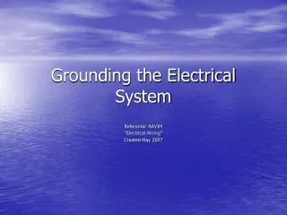
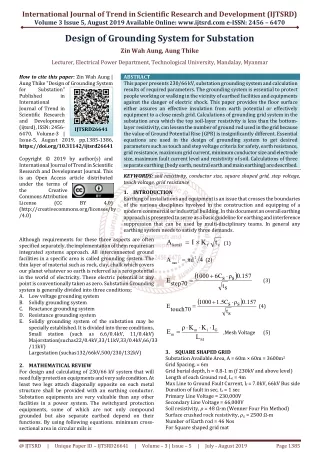
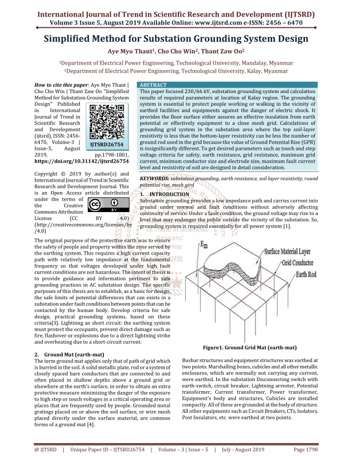
International Journal of Trend in Scientific Research and Development (IJTSRD) Volume 3 Issue 5, August 2019 Available Online: www.ijtsrd.com e-ISSN: 2456 – 6470 Simplified Method for Substation Grounding System Design Aye Myo Thant1, Cho Cho Win2, Thant Zaw Oo2 1Department of Electrical Power Engineering, Technological University, Mandalay, Myanmar 2Department of Electrical Power Engineering, Technological University, Kalay, Myanmar How to cite this paper: Aye Myo Thant | Cho Cho Win | Thant Zaw Oo "Simplified Method for Substation Grounding System Design" Published in International Journal of Trend in Scientific Research and Development (ijtsrd), ISSN: 2456- 6470, Volume-3 | Issue-5, August 2019, https://doi.org/10.31142/ijtsrd26754 Copyright © 2019 by author(s) and International Journal of Trend in Scientific Research and Development Journal. This is an Open Access article distributed under the terms of the Creative Commons Attribution License (CC (http://creativecommons.org/licenses/by /4.0) The original purpose of the protective earth was to ensure the safety of people and property within the zone served by the earthing system. This requires a high current capacity path with relatively low impedance at the fundamental frequency so that voltages developed under high fault current conditions are not hazardous. The intent of thesis is to provide guidance and information pertinent to safe grounding practices in AC substation design. The specific purposes of this thesis are to establish, as a basic for design, the safe limits of potential differences that can exists in a substation under fault conditions between points that can be contacted by the human body. Develop criteria for safe design, practical grounding systems, based on these criteria[3]. Lightning an short circuit: the earthing system must protect the occupants, prevent direct damage such as fire, flashover or explosions due to a direct lightning strike and overheating due to a short-circuit current. 2.Ground Mat (earth-mat) The term ground mat applies only that of path of grid which is burried in the soil. A solid metallic plate, rod or a system of closely spaced bare conductors that are connected to and often placed in shallow depths above a ground grid or elsewhere at the earth’s surface, in order to obtain an extra protective measure minimizing the danger of the exposure to high step or touch voltages in a critical operating area or places that are frequently used by people. Grounded metal gratings placed on or above the soil surface, or wire mesh placed directly under the surface material, are common forms of a ground mat [4]. ABSTRACT This paper focused 230/66 kV, substation grounding system and calculation results of required parameters at location of Kalay region. The grounding system is essential to protect people working or walking in the vicinity of earthed facilities and equipments against the danger of electric shock. It provides the floor surface either assures an effective insulation from earth potential or effectively equipment to a close mesh grid. Calculations of grounding grid system in the substation area where the top soil-layer resistivity is less than the bottom-layer resistivity can be less the number of ground rod used in the grid because the value of Ground Potential Rise (GPR) is insignificantly different. To get desired parameters such as touch and step voltage criteria for safety, earth resistance, grid resistance, maximum grid current, minimum conductor size and electrode size, maximum fault current level and resistivity of soil are designed in detail consideration. KEYWORDS: substation grounding, earth resistance, soil layer resistivity, round potential rise, mesh gird 1.INTRODUCTION Substation grounding provides a low impedance path and carries current into ground under normal and fault conditions without adversely affecting continuity of service. Under a fault condition, the ground voltage may rise to a level that may endanger the public outside the vicinity of the substation. So, grounding system is required essentially for all power system [1]. IJTSRD26754 pp.1798-1801, BY 4.0) Figure1. Ground Grid Mat (earth-mat) Busbar structures and equipment structures was earthed at two points. Marshalling boxes, cubicles and all other metallic enclosures, which are normally not carrying any current, were earthed. In the substation Disconnecting switch with earth-switch, circuit breaker, Lightning arrester, Potential transformer, Current transformer, Power transformer, Equipment’s body and structures, Cubicles are installed compactly. All of these are grounded at the body of structure. All other equipments such as Circuit Breakers, CTs, Isolators, Post Insulators, etc. were earthed at two points. @ IJTSRD | Unique Paper ID – IJTSRD26754 | Volume – 3 | Issue – 5 | July - August 2019 Page 1798
International Journal of Trend in Scientific Research and Development (IJTSRD) @ www.ijtsrd.com eISSN: 2456-6470 3.Design Characteristics For 230/66kV substation, 100MVA outdoor AIS substation. Need to calculate the deliverable single line to ground fault current of substation. And related transmission line impedance Z1, Z2, Z0(R+jXL) values from hand calculation. Soil resistivity can be determine with visual inspection or proper measurement devices (Four Pin Earth Tester)[3]. It plotted to measure the following model. For square shaped Grid/Mat as bellows; = × A I K ct kcmil f Equation (1) Switchyard surface layer is crushed rock 4”(0.102m) thickness, with resistivity of 2500 Ω m, and for an actual inner resistivity of 48Ω.m by four pin tester. The reflection factor K is computed using the following equation; ρ ρ K + Linemen or operator body’s weight can be expected at least70kg, (assume RB:1000Ω). So that, consider the permissible/ tolerable step and touch voltage initially. Fault current, If = 3I0, V 3 × = − s = ρ ρ s Equation (2) (1) 3 + × + + + + + 3 R (R R R ) j(X X X ) f 1 2 0 1 2 3 where; Km = geometrical factor, ρ= the soil resistivity, a corrective factor, IG = maximum grid current For square shaped mat design ( 1 h0= (usually constant) h 1 h 0.644 i Mesh Voltage; K K I ρ E The effective buried conductor length (Ls); (with or without ground rods) ( R C s ( + ⋅ D h D h 2 π Step Voltage; Es I t s ρ s E Earthing grid resistance The Schwarz equations that are modeling the effect of earthing rods or electrodes shown as below[2]. 2 m R 2 1 g − + Touch voltage limit-the maximum potential differene between the surface potential and potential of an earth conducting structure during a fault due to ground potential rise. Figure2. Six Locations for Earth Resistivity Measurement Table1. Soil Resistivity Measurement Record Table Test Pin Spacing Direction 1 4 Direction 2 4 Direction 3 4 Direction 4 4 Direction 5 4 Direction 6 4 ) d 2 2 K + 1 D D 2h h 8 ii = + − + ⋅ K h ln ln ( ( ) ) m Meter Display Ohm-meter 65 33 60 36 56 40 ⋅ ⋅ ⋅ ⋅ ⋅ ⋅ − 2π 16 h d 8 D 4 d K 2 n 1 π Location Remark h = K 1.0 ii (with rods), = + K Avg 48 Ω-m h 0 ( ) = + ⋅ K 0.148 n Irregularity factor; Substation Available Area, A = 60m × 60m = 3600m2 Grid Spacing, D = 6m Grid burial depth, h = 0.8-1 m (for 230kV and above level) Length of each Ground rod, Lr = 4m Max Line to Ground Fault Current, If = 7.0kV, 66kV Bus side Duration of fault in sec, tc = 1 sec Primary Line Voltage = 230,000V Secondary Line Voltage = 66,000V Soil resistivity, = 48 Ω-m (Wenner Four Pin Method) Surface crushed rock resistivity, Number of Earth rod = 46 Nos × × × = G m i m L + + × × r L 1.55 1.22 L C R 2 2 + L L x y ) = + L 0.75L 0.85L ) 1 1 1 1 − n 2 = + + − K 1 0.5 s Equation (3) (1) = 2500 Ω-m ⋅ ⋅ ⋅ K K G = L s Equation (4) 1 1 1 = + + 1 ρ Rg h L1 20A + 1 20 A Equation (5) − R R = R R R 2R m Equation (6) 1 2 Figure3. Preliminary Calculation of Touch and Step Voltage @ IJTSRD | Unique Paper ID – IJTSRD26754 | Volume – 3 | Issue – 5 | July - August 2019 Page 1799
International Journal of Trend in Scientific Research and Development (IJTSRD) @ www.ijtsrd.com eISSN: 2456-6470 Etouch(50kg) = (RB+1.5ρ)*IB(50) Etouch(50kg) =(1000+1.5Csρs)*IB(50) Etouch(70kg) = (RB+1.5ρ)*IB (70) Etouch(70kg) = (1000+1.5Csρs)*IB (70) Equation(10) Step voltage limit-the maximum difference in surface potential experienced by a person bridging a distance of 1m with the feet without contact to any earthed object. 0.116 B 0.157 B Estep(50kg) = (RB+6ρ)*IB(50) Equation (13) Estep(50kg) = (1000+6Csρs)*IB(50) Estep(70kg) = (RB+6ρ)*IB(50) Equation (15) Estep(70kg) = (1000+6Cs ρs)*IB(50) The minimum conductor size capable of withstanding adiabatic temperature rise associated with earth fault, Amm2 1 If Equation (7) as small as size 4.74mm could be used but due to the mechanical strength and ruggedness requirements, a larger size, d=15mm is usually as a minimum for future fault level and future generation capacity. In this case, dmin = 15-16 mm, standard copper wire is should be choice for better grid. In view of the above results, the earth mat design and configuration is successful and completed as shown in tables. Table2. Comparison of Permissible and Designed Values Equation (8) Equation (9 ) Permissible/ Allowed <2553V <804.7V 1 Ω Designed = I t For 50kg, Equation (11) Step Voltage (Es) Mesh Voltage(Em) Grid Resistance, Rg Earth Mat Design is safe and Completed 119.46V 179.44V 0.38 Ω s = I t For 70kg, Equation (12) s Table3. Result Table for Substation Grounding System Reflection factor (K) Reduction factor (Cs) Step voltage (Estep70) Touch voltage (Etouch70) Total length of all earth rod (LR) Total length of horizontal conductor (LC) Parameter length of grid conductor (Lg) Total ground conductor length (LT) Grid resistance (Rg) Grid current (IG) Ground Potential Rise (GPR) Geometrical factor (Km) Irregularity factor (Ki) Mesh voltage (Em) Effective buried conductor length (Ls) Step voltage (Estep) Conclusions The grounding system in a substation consists of a minimum of four earth electrodes installed around the inside perimeter of the substation and connected together with the earth mesh the exact spacing of the electrodes which will be based on local conditions, resistivity of the area and space available for electrodes. The spacing between should be greater than the electrodes’ length. Although the earth mesh will often result in a low enough resistance without the use of electrodes, fifty electrodes are still necessary in this to ensure the fault level capability and forty-six electrodes are used for neutral ground grid. Electrodes are also required in case of the drying out of the soil at the depth of the earth mesh in long dry spells. The size of the high voltage grounding conductors is determined by the earth fault level but in any case shall be not smaller than 70 mm2 copper. The size of the main grounding conductor shall not be smaller than 25 mm2 copper. Acknowledgements The author is deeply grateful to Prof. Dr. Yadana Aung, Head of Electrical Power Engineering Department, Technological University (Mandalay) for her kindly permission and encouragement. The author is deeply grateful to her teachers Equation (14) -0.96 0.7 2553V 804.7V 184m 1320m 240m 1504m 0.38Ω 4200A 1596V 0.633 2.272 179.44V 1153.2 119.46V Equation (16) = × − 4 + × TCPA 10 K0 Tm Ln + ρr tc Ko Ta αr Equation (17) Where; TCAP = temperature capacity per unit volume, αr = thermal co-eff of resistivity, ρr = resistivity of ground conductor, Ta = ambient temperature,Tm = maximum allowable temperature The diameter of the grid conductor, 2 mm d = Equation (18) 4.Results and Discussion The large substation, the ground resistance is usually about 1Ω of less. In smaller distribution substation the usually acceptable range is from 1 to 5Ω, depending on local conditions in table (1).The designation of step voltage, mesh voltage and ground resistance are expressed in comparison situation. The effective buried conductor length; without ground rods), length or grid conductor, ground conductor, grid current, grid resistance, ground potential rise are focused consideration on existing substation data. In this calculation, a tolerance of parameters. The result GPR value is very important and it should be less then permissible touch voltage in table (2). Because of consideration, switchyard surface layer is crushed rock 4”(0.102m) thickness, with resistivity of 2500 Ω m, and for an actual inner resistivity of 48Ω.m by four pin tester and Resistivity of surface crushed rock causes to a reduction factor Cs. Linemen/Operator body’s weight can be expected at least70kg, (Assume RB:1000Ω). So that, consider the permissible/ tolerable step and touch voltage initially. Finally, this allowed value will decide the obtained a safe limit design. Amm2 based on this computation, a copper wire × 4 A π (with or is assumed in all ± 5 % @ IJTSRD | Unique Paper ID – IJTSRD26754 | Volume – 3 | Issue – 5 | July - August 2019 Page 1800
International Journal of Trend in Scientific Research and Development (IJTSRD) @ www.ijtsrd.com eISSN: 2456-6470 [3]John D. Mc Donald, Electrical Power Substation Engineering, (2003). who are working in Electrical Power Engineering Department, Technological University (Kalay) for their willingness to share of ideas and helpful suggestions on throughout the research. References [1]Donald, N.L.IEEE Guide for safety in AC Substation Grounding, IEEE-SA Stand board, New York, (2000). [4]Garrett, D.L. Guideline for the Design, Installation, Testing and Maintenance of Main Earthing System in Substation, Electricity Association, (1992) [5]Chairman of IEEE Standards Board; IEEE Guide for Measuring Earth Resistivity, Ground Impedance, and Earth Surface Potentials of Ground System, (1983) [2]IEEE guide for safety in AC substation Grounding, IEEE 80-2000. @ IJTSRD | Unique Paper ID – IJTSRD26754 | Volume – 3 | Issue – 5 | July - August 2019 Page 1801