Download
1 / 6
60 likes | 70 Vues
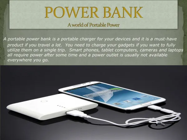
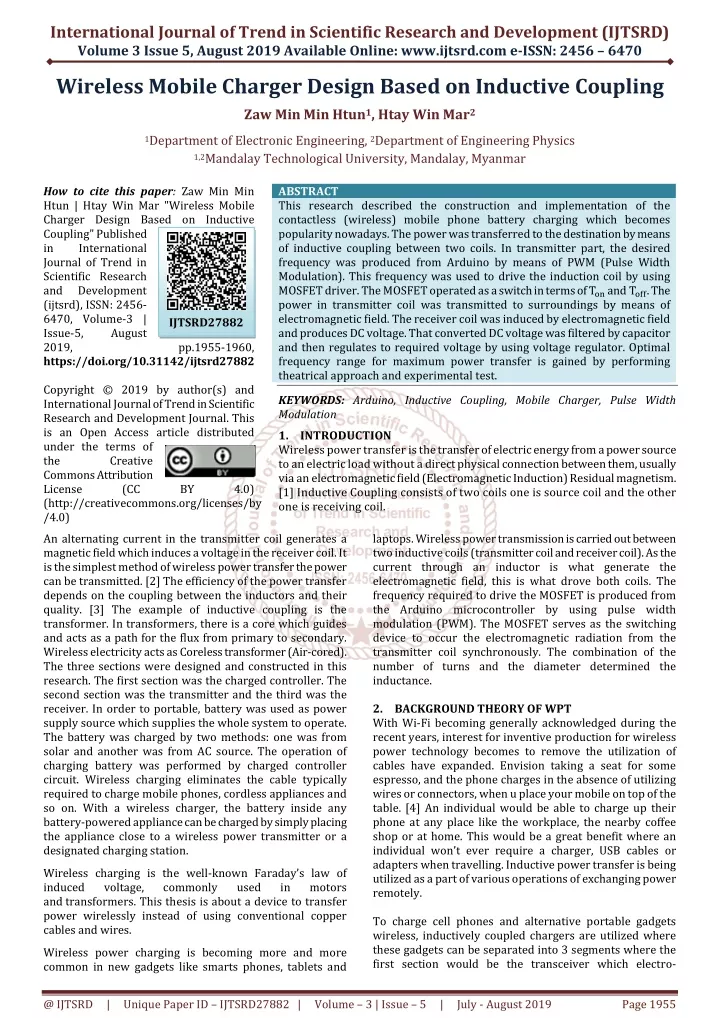
This research described the construction and implementation of the contactless wireless mobile phone battery charging which becomes popularity nowadays. The power was transferred to the destination by means of inductive coupling between two coils. In transmitter part, the desired frequency was produced from Arduino by means of PWM Pulse Width Modulation . This frequency was used to drive the induction coil by using MOSFET driver. The MOSFET operated as a switch in terms of T on and T off. The power in transmitter coil was transmitted to surroundings by means of electromagnetic field. The receiver coil was induced by electromagnetic field and produces DC voltage. That converted DC voltage was filtered by capacitor and then regulates to required voltage by using voltage regulator. Optimal frequency range for maximum power transfer is gained by performing theatrical approach and experimental test. Zaw Min Min Htun | Htay Win Mar "Wireless Mobile Charger Design Based on Inductive Coupling" Published in International Journal of Trend in Scientific Research and Development (ijtsrd), ISSN: 2456-6470, Volume-3 | Issue-5 , August 2019, URL: https://www.ijtsrd.com/papers/ijtsrd27882.pdf Paper URL: https://www.ijtsrd.com/engineering/electronics-and-communication-engineering/27882/wireless-mobile-charger-design-based-on-inductive-coupling/zaw-min-min-htun<br>

E N D
International Journal of Trend in Scientific Research and Development (IJTSRD) Volume 3 Issue 5, August 2019 Available Online: www.ijtsrd.com e-ISSN: 2456 – 6470 Wireless Mobile Charger Design Based on Inductive Coupling Zaw Min Min Htun1, Htay Win Mar2 1Department of Electronic Engineering, 2Department of Engineering Physics 1,2Mandalay Technological University, Mandalay, Myanmar How to cite this paper: Zaw Min Min Htun | Htay Win Mar "Wireless Mobile Charger Design Based on Inductive Coupling" Published in International Journal of Trend in Scientific Research and Development (ijtsrd), ISSN: 2456- 6470, Volume-3 | Issue-5, August 2019, https://doi.org/10.31142/ijtsrd27882 Copyright © 2019 by author(s) and International Journal of Trend in Scientific Research and Development Journal. This is an Open Access article distributed under the terms of the Creative Commons Attribution License (CC (http://creativecommons.org/licenses/by /4.0) An alternating current in the transmitter coil generates a magnetic field which induces a voltage in the receiver coil. It is the simplest method of wireless power transfer the power can be transmitted. [2] The efficiency of the power transfer depends on the coupling between the inductors and their quality. [3] The example of inductive coupling is the transformer. In transformers, there is a core which guides and acts as a path for the flux from primary to secondary. Wireless electricity acts as Coreless transformer (Air-cored). The three sections were designed and constructed in this research. The first section was the charged controller. The second section was the transmitter and the third was the receiver. In order to portable, battery was used as power supply source which supplies the whole system to operate. The battery was charged by two methods: one was from solar and another was from AC source. The operation of charging battery was performed by charged controller circuit. Wireless charging eliminates the cable typically required to charge mobile phones, cordless appliances and so on. With a wireless charger, the battery inside any battery-powered appliance can be charged by simply placing the appliance close to a wireless power transmitter or a designated charging station. Wireless charging is the well-known Faraday’s law of induced voltage, commonly and transformers. This thesis is about a device to transfer power wirelessly instead of using conventional copper cables and wires. Wireless power charging is becoming more and more common in new gadgets like smarts phones, tablets and ABSTRACT This research described the construction and implementation of the contactless (wireless) mobile phone battery charging which becomes popularity nowadays. The power was transferred to the destination by means of inductive coupling between two coils. In transmitter part, the desired frequency was produced from Arduino by means of PWM (Pulse Width Modulation). This frequency was used to drive the induction coil by using MOSFET driver. The MOSFET operated as a switch in terms of T?? and T???. The power in transmitter coil was transmitted to surroundings by means of electromagnetic field. The receiver coil was induced by electromagnetic field and produces DC voltage. That converted DC voltage was filtered by capacitor and then regulates to required voltage by using voltage regulator. Optimal frequency range for maximum power transfer is gained by performing theatrical approach and experimental test. KEYWORDS: Arduino, Inductive Coupling, Mobile Charger, Pulse Width Modulation 1.INTRODUCTION Wireless power transfer is the transfer of electric energy from a power source to an electric load without a direct physical connection between them, usually via an electromagnetic field (Electromagnetic Induction) Residual magnetism. [1] Inductive Coupling consists of two coils one is source coil and the other one is receiving coil. IJTSRD27882 pp.1955-1960, BY 4.0) laptops. Wireless power transmission is carried out between two inductive coils (transmitter coil and receiver coil). As the current through an inductor is what generate the electromagnetic field, this is what drove both coils. The frequency required to drive the MOSFET is produced from the Arduino microcontroller by using pulse width modulation (PWM). The MOSFET serves as the switching device to occur the electromagnetic radiation from the transmitter coil synchronously. The combination of the number of turns and the diameter determined the inductance. 2.BACKGROUND THEORY OF WPT With Wi-Fi becoming generally acknowledged during the recent years, interest for inventive production for wireless power technology becomes to remove the utilization of cables have expanded. Envision taking a seat for some espresso, and the phone charges in the absence of utilizing wires or connectors, when u place your mobile on top of the table. [4] An individual would be able to charge up their phone at any place like the workplace, the nearby coffee shop or at home. This would be a great benefit where an individual won’t ever require a charger, USB cables or adapters when travelling. Inductive power transfer is being utilized as a part of various operations of exchanging power remotely. To charge cell phones and alternative portable gadgets wireless, inductively coupled chargers are utilized where these gadgets can be separated into 3 segments where the first section would be the transceiver which electro- used in motors @ IJTSRD | Unique Paper ID – IJTSRD27882 | Volume – 3 | Issue – 5 | July - August 2019 Page 1955
International Journal of Trend in Scientific Research and Development (IJTSRD) @ www.ijtsrd.com eISSN: 2456-6470 magnetically exchanges power by means of inductive loops that provide a wireless exchange of power to receiving components. [5] Inductive coupling would be second section which would be the antenna and is forwarded to the bridge rectifiers which change the induced AC voltage to DC voltage. Last section would be rectifier which provides DC voltage to load. Fig 1 shows the classification of wireless power transfer. is good enough to be used as conducting wire. AWGs were shown in Table 2. Table2. American Wire Gauge System for Copper Wire AWG Gauge Diameter(mm) Ampacity(A) 30 0.30 28 0.36 26 0.46 24 0.51 22 0.78 3.3 MOSEFT DRIVER (IRFZ44N) The metal-oxide-semiconductor field-effect transistor (MOSFET, MOS-FET, or MOS FET) is a type of field-effect transistor (FET), most commonly fabricated by the controlled oxidation of silicon. It has an insulated gate, whose voltage determines the conductivity of the device. This ability to change conductivity with the amount of applied voltage can be used for amplifying or switching electronic signals. A metal-insulator-semiconductor field- effect transistor or MISFET is a term almost synonymous with MOSFET. Another synonym is IGFET for insulated-gate field-effect transistor. To drive the inductive coil with 12 V DC supply, a IRFZ44N n-channel MOSFET is used. This MOSFET consists of 55 V maximum Drain to Source voltage which is enough to handle 12 V feed and 49 A. The drain current is also sufficient to draw 3 A current. This MOSFET can be easily driven by Arduino 5 V output because its VGS (threshold) has a voltage range of 2V-4V. For n-channel MOSFET, gate pulse voltage is required to be higher than threshold range. A IRFZ44N MOSFET has three pins. The first pin is the gate, the second pin is the drain and the third pin is the source. General description of IRFZ44N is that N-channel enhancement mode standard level field-effect power transistor in a plastic envelope using ‘trench’ technology. The device features very low on-state resistance and has integral Zener diodes giving ESD protection up to 2kV. 4.DESIGN CONSIDERATION 4.1 HARDWARE IMPLEMENTATION The hardware designing consisted of three main sections. They were the power supply section, the transmitter section and the receiver section. General block diagrams are shown in Fig. 2 and 3. 0.80 1.25 3.50 5.00 8.73 Fig.1. Classification of wireless power transfer 3.DEVICE SELECTION 3.1 MICROCONTROLLER Arduino Uno is a microcontroller board that is based on ATmega328P. Arduino UNO consists of 14 digital input/output pins (where 6 pins can be used as PWM outputs), 6 analog inputs, a 16 MHz quartz crystal, a USB connection, a power jack, an ICSP header and a reset button. Arduino UNO is selected for this project because only 1 analog pin is used as analog reading and 1 pin as digital PWM output is required and the required maximum frequency of 1MHz is much lower than its quartz crystal which is 16 MHz. Description of the Arduino UNO as it is stated in its datasheet is given in Table 1. Table1 Technical feature of Arduino UNO Microcontroller Operation Voltage Input Voltage(Vin) Input Voltage(limit) Digital I/O Pins PWM Digital I/O Pins Analog Input Pins DC Current per I/O Pin DC Current for 3.3V Pin ATmega328P 5V 7-12V 6-20V 14(of which 6 are PWM) 6 6 20mA 50mA 32KB of which 0.5KB used by bootloader 2KB 1KB 16MHz Flash Memory SRAM EEPROM Clock Speed 3.2 To cover 3A current draw, A 26 Automatic Wire Gauge (AWG) standards is utilized since it is able handle a current of 3.5A. Figure illustrates other AWGs and their corresponding ratings. American wire gauge (AWG), also known as the Brown & Sharpe wire gauge, is a logarithmic stepped standardized wire gauge system used since 1857 predominantly in North America for the diameters of round, solid, nonferrous, electrically conducting wire. The copper is used as the conduction wires because of its conductivity that Figure.2. Block Diagram of the System (Transmitter) INDUCTIVE COIL In power supply section, the battery was used to supply the whole system. The voltage regulator was used to regulate the DC voltage to required voltage level. The battery charging method was Solar-Grid Line hybrid charging method. In transmitter section, the frequency was produced from the microcontroller by means of PWM (Pulse Width Modulation). The MOSFET driver was used as switching device for driving the inductive coil. The potentiometer was used to select the desired frequency. @ IJTSRD | Unique Paper ID – IJTSRD27882 | Volume – 3 | Issue – 5 | July - August 2019 Page 1956
International Journal of Trend in Scientific Research and Development (IJTSRD) @ www.ijtsrd.com eISSN: 2456-6470 permeability and conductivity of the medium. The skin depth decreases with higher frequency. The skin depth, 1 δ (2) πfμσ Where, = conductivity of the material (5.8 δ= skin depth μ= permeability of material (4π 7 10 for Copper) Figure.3. Block Diagram of the System (Receiver) In receiver section, the receiver coil received the radiated electromagnetic field and converted to DC voltage to charge mobile phones. The complete circuit diagrams are shown in Fig. 4 and 5. 10) 7 μ 0μ μ = permeability (F/m) = μ = Permeability of air = (4π μ = 1 for Copper, Aluminum, Gold, etc. From the equation (2), r 10) (h/m) 7 0 r 1 δ 7 7 7 π 122.6 10 4π 10 5.8 10 = 0.188cm = 0.0188cm The diameter of electrical wire is expressed as the American Wire Gauge AWG number. The gauge number is inversely proportional to the diameter of the coil. 1 AWG In theoretical result, the gauge of the copper wire was 26.4 Gauge. Therefore, 26-gauge wire was chosen in this work. 4.2.2. Calculation of Coil Inductance In this research work, supply voltage, V = 12V and supply current, I = 3A. V = IR (Ohm’s Law) X?= R =? X?= 4Ω X? = ωL X?=2πfL L = (4) Where, f = 100kHz,500kHz and 1MHz Substituting these frequencies into Equation (4), L = 6.36µH, L = 1.27µH and L = 0.636µH are obtained. So, the minimum value of inductance value is 0.636µH at frequency 1000kHz and the maximum value is 6.36µH at 1000 kHz. 4.2.3. Calculation of Number of Turns The number of turns of the air-core inductive coil could be calculated by using the Equation (6). 26.4 = Figure.4. Circuit diagram of the System (Transmitter) 2 0.0188 LM323 regulator is applied for suppling Arduino and I2C LCD. Potentiometer is attached on A0 pin and voltage sensing circuit is connected to A1 pin of Arduino. Pin 9 is used as PWM output for driving MOSFET driver circuit. (3) ?, ?? ?π? Figure5. Circuit diagram of the System (Receiver) For eliminate negative part, bridge diode is applied and capacitor filtering makes output be stable. The output voltage level is measured by voltage divider and Arduino controller. 5V regulator IC or buck converter can be applied for USB charging. 4.2 DESIGN CALCULATION To calculate the size of the air-core coil, the distance between the transmitter and receiver was assumed 3cm. To calculate the radius of the air core coil, z 2 a Where, Distance, z = 3cm Radius of the coil, a = 4.24cm In this system, the diameter of the coil was chosen 3.175cm. 4.2.1. Calculation of the Gauge of Copper Wire Coil The skin depth determines the effective current carrying area of the coil and is a function of frequency and (1) Figure6. Air-Core Coil with Multilayer @ IJTSRD | Unique Paper ID – IJTSRD27882 | Volume – 3 | Issue – 5 | July - August 2019 Page 1957
International Journal of Trend in Scientific Research and Development (IJTSRD) @ www.ijtsrd.com eISSN: 2456-6470 ?.??(??)? ????????? (µ L= Where, a = average radius of coil (cm), b = winding thickness (cm), h = winding height (cm) N=number of turns, L=inductance Substituting the values of inductance, L = 6.36µH, L = 1.27µH and L = 0.636µH For ? = 6.36µH, N = 6.64 turns~ 7 turns For ? = 1.27 µH, N = 2.96 turns~ 3 turns For ? = 0.64µH, N = 0.78 turns~ 1 turns So, the number of turns in secondary coil was chosen ?? = 6 turns. And then, substituting the ?? = 6 turns in Equation (5).Therefore, the value of inductance ?? = 5.19µ? was obtained. Note: Choosing the lower number of turns will lead to the short circuit. The supply voltage for primary coil 6 turns was 12V. If the efficiency was 100%, all supply voltage 12V will induced. But, according to Literature Review, in wireless power transfer the efficiency for 100% is not possible. Only 10% to 50% is possible. Therefore, the number of turns in secondary coil is increased to get greater inductance. The number of turns in secondary coil ?? is assumed 12 turns. Substituting ?? = 12 ????? in Equation (5), the value of inductance in secondary coil,?? = 20.76 µ?is obtained. 4.2.4.Calculation of Effective Frequency The frequency of the transmitter coil could be calculated by using the Equation (6). ?? = ω ??=2??? X f (5) Figure.7. Flowchart for the Arduino program 5.SIMULATION Proteus simulation is used for the whole system as shown in Fig. 8. In simulation, the result of the frequency output and the input voltage from the battery was shown on I2C LCD display. The frequency could be adjusted. (6) L 2ππ where, Number of turns N = 6 turns inductance of primary coil L = 5.19µ? reactance of inductor ?? = 4 Ω Therefore, f = 122.6 kHz 4.3.SOFTWARE IMPLEMENTATION The program for the control system is written by the Arduino IDE and uploaded to the Arduino Uno to operate PWM generation as described in the program. The flow chart of the program is shown in Fig. 7. At the start of the program, 50% duty cycle is setup. As the looping of the system, analog reading is performed and 10 bit resolution (0 to 1023) to 100 Hz to 1MHz conversion is performed accordingly. Then PWM is generated and input voltage measurement is performed for analytical record and is displayed on LCD. Figure.8 Simulation result for Transmitter Section The frequency was generated from the microcontroller by using PWM modulation. The Arduino microcontroller contains built-in crystal oscillator which can produce the frequency up to 16MHz. In this system, the frequency produced was in the range of 100kHz to 1000kHz. The PWM waveform output of simulation is shown in Fig.9. @ IJTSRD | Unique Paper ID – IJTSRD27882 | Volume – 3 | Issue – 5 | July - August 2019 Page 1958
International Journal of Trend in Scientific Research and Development (IJTSRD) International Journal of Trend in Scientific Research and Development (IJTSRD) @ www.ijtsrd.com www.ijtsrd.com eISSN: 2456-6470 As practical experiment, the generated frequency is displayed on LCD as shown in Fig. 13. This condition points out the maximum frequency of 999 kHz. As practical experiment, the generated frequency is displayed on LCD as shown in Fig. 13. This condition points out the maximum frequency of 999 kHz. Figure.9 PWM Waveform Output 9 PWM Waveform Output Figure.13 Frequency Generated 13 Frequency Generated From Transmitter And the applied frequency is measured by using the oscilloscope as shown in Fig. 14. This figure shows 500 kHz PWM output for inductive coil. And the applied frequency is measured by using the oscilloscope as shown in Fig. 14. This figure shows 500 kHz PWM output for inductive coil. Figure.10 Displaying Voltage by using Microcontroller 10 Displaying Voltage by using Microcontroller Fig. 10 showed the displaying voltage at receiver section. The voltage sensing was operated by using the voltage divider circuit and analog reading because the voltage input of Arduino pins is limited at maximum voltage 5V. In this side16x2 LCD is applied for output voltage signal display. 6.EXPERIMENTAL TEST Experimental test were carried out and the results can be seen in the following figures. Fig. 10 showed the displaying voltage at receiver section. was operated by using the voltage divider circuit and analog reading because the voltage input of Arduino pins is limited at maximum voltage 5V. In this side16x2 LCD is applied for output voltage signal display. Experimental test were carried out and the results can be Figure.14 Testing Frequency of 500kHz 14 Testing Frequency of 500kHz Figure11 Experimental Test for Power Transfer 11 Experimental Test for Power Transfer Fig. 11 shows the complete constructed circuit in which transmitter and receiver are included. Fig. 12 represented the charging state for mobile phone. Fig. 11 shows the complete constructed circuit in which transmitter and receiver are included. Fig. 12 represented Figure.15 Testing the Voltage between Transmitter Coil Terminals Coil Terminals Fig 15 represents the ripple ac voltage between transmitter coil terminals. Although the system supply voltage is 12 V, the ripple voltage increased due to oscillation. 15 Testing the Voltage between Transmitter Fig 15 represents the ripple ac voltage between transmitter coil terminals. Although the system supply voltage is 12 V, the ripple voltage increased due to oscillation. Figure.12 Testing Phone Charging 12 Testing Phone Charging @ IJTSRD | Unique Paper ID – IJTSRD278 27882 | Volume – 3 | Issue – 5 | July - August 2019 August 2019 Page 1959
International Journal of Trend in Scientific Research and Development (IJTSRD) @ www.ijtsrd.com eISSN: 2456-6470 7.CONCLUSIONS AND DISCUSSION In this work, wireless charging system by using inductive coupling was designed and constructed. There was a growing market to construct the wireless charging system in the various kinds of electronic devices. There were many kinds of methods in wireless charging system. Among them, inductive coupling method was the simplest method. The system used Arduino microcontroller to produce the required frequency for driving the induction coil because it gave more accurate frequency than other controllers. In this circuit, N channel mode MOSFET IRFZ44N was used for driving the inductive coil because of its accurate switching timing and ratings. An important issue associated with all wireless power systems was limiting the exposure of people and other living things electromagnetic fields. Finally, the wireless charger for mobile phones became an important role of human life style because of its simple design and safety for humans. The most powerful output can be obtained at switching frequency of 100 kHz for the design shown in earlier sections. 8.Acknowledgement The authors would like to acknowledge particular thanks to department heads of Electronic Engineering and Engineering Physics, for their accomplished guidance, their willingness to share ideas and helpful suggestions throughout the research work. References [1]Do Lam Mung: Design And Construction Of Wireless Charging System Using Inductive Coupling, June, 2015, EC department, Mandalay Technological University Figure.16 Testing the Voltage between Receiver Coil Terminals Fig 16 shows output voltage gained by regulator voltage at receiver circuit for no load condition. In this condition the current depends on the charged battery. If the battery is much closed to fully charged condition, the current draw will be definitely reduced as shown in Fig 17. to potentially injurious [2]Ajey, Kumar, R., Gayathri. H.R., Bette Gowda,R. and Yashwanth,B.: WiTricity: Wireless Power Transfer By Non-radiative Method, International Journal of Engineering Trends and Technology (IJETT) – 11 (6) - May (2014). Figure.17 Current Produced at Receiver Section The power delivered from transmitter coil at each frequency was shown in Table III. When frequency decreases, the power delivered from the coil increases. The delivered power is maximum at 122.6 kHz. Table.3 Power Delivered from Transmitter Coil at Each Frequency [3]Marian, K. K.: Fundamentals of Magnetic Devices, High- Frequency Magnetic Components, Second Edition, Published 2014 by John Wiley & Sons, Ltd. Companion Website: P=VI [4]Rui Zhang: Wireless Powered Communication Frequency Voltage Current Power Delivered 45W 57.6W 68W 72W 98.7W 84.5W Opportunities and Challenges, ECE Department, National University of Singapore ICC (2014). 500kHz 400kHz 300kHz 200kHz 122.6kHz 100kHz 30V 32V 34V 34.78V 47V 30.17V 1.5A 1.8A 2A 2.07A 2.1A 2.8A [5]Varun Nagoorkar: Midrange Magnetically-Coupled Resonant Circuit Wireless Power Transfer, The University of Texas at Tyler, April 11th, (2014). @ IJTSRD | Unique Paper ID – IJTSRD27882 | Volume – 3 | Issue – 5 | July - August 2019 Page 1960