Download
1 / 5
50 likes | 56 Vues
A Micro grid MG is a local energy system consisting of a number of energy sources e.g., wind turbine or solar panels among others , energy storage units, and loads that operate connected to the main electrical grid or autonomously. MGs provide flexibility, reduce the main electricity grid dependence, and contribute to changing large centralized production paradigm to local and distributed generation. However, such energy systems require complex management, advanced control, and optimization. Moreover, the power electronics converters have to be used to correct energy conversion and be interconnected through a common control structure is necessary. A classical droop control system is often implemented in MG. It allows correct operation of parallel voltage sourced converters in grid connection, as well as islanded mode of operation. However, it requires complex power management algorithms, especially in islanded MGs, which balance the system and improves reliability. The novel reactive power sharing algorithm is developed, which takes into account the parameters of the converter as apparent power limit and maximum active power. The developed solution is verified in simulation and compared with other known reactive power control methods. G. Amulya | Dr. S. V. D. Anil Kumar "Dealing With Reactive Power in Islanded Micro Grid-Corresponding Power Distribution in Hierarchical Droop Control using Photovoltaic System" Published in International Journal of Trend in Scientific Research and Development (ijtsrd), ISSN: 2456-6470, Volume-3 | Issue-5 , August 2019, URL: https://www.ijtsrd.com/papers/ijtsrd26498.pdf Paper URL: https://www.ijtsrd.com/engineering/electrical-engineering/26498/dealing-with-reactive-power-in-islanded-micro-grid-corresponding-power-distribution-in-hierarchical-droop-control-using-photovoltaic-system/g-amulya<br>

E N D
International Journal of Trend in Scientific Research and Development (IJTSRD) Volume 3 Issue 5, August 2019 Available Online: www.ijtsrd.com e-ISSN: 2456 – 6470 Dealing With Reactive Power in Islanded Micro Grid-Corresponding Power Distribution in Hierarchical Droop Control using Photovoltaic System G. Amulya1, Dr. S. V. D. Anil Kumar2 1M.Tech Scholar, 2Professor 1,2St.Ann's College of Engineering & Technology, Chirala, Andhra Pradesh, India How to cite this paper: G. Amulya | Dr. S. V. D. Anil Kumar "Dealing With Reactive Power in Islanded Corresponding Power Distribution in Hierarchical Droop Photovoltaic System" Published in International Journal of Trend in Scientific Research and Development (ijtsrd), ISSN: 2456- 6470, Volume-3 | Issue-5, August 2019, https://doi.org/10.31142/ijtsrd26498 Copyright © 2019 by author(s) and International Journal of Trend in Scientific Research and Development Journal. This is an Open Access article distributed under the terms of the Creative Commons Attribution License (CC (http://creativecommons.org/licenses/by /4.0) Recent interest in distributed generator installation into low voltage busses near electrical consumers has created some new challenges for protection engineers that are different from traditional radically based protection methodologies. Therefore, typical protection configurations need to be re- thought such as re-closures out-of-step monitoring, impedance relay protection zones with the detection of unplanned islanding of distributed generator systems. The condition of islanding, defined as when a section of the nonutility generation system is isolated from the main utility system, is often considered undesirable because of the potential damage to existing equipment, utility liability concerns, reduction of power reliability and power quality. Human progress has been linked to the increase in energy consumed per capita. In the last 20 years, electrical consumption has been steadily increasing in North America at a rate of 1.1% for Canada, and 2.0% for the United States; However, the investment into new bulk electric power sources such as hydro dams and nuclear generation plants has become politically, economically and physically limited. For example, transmission investment in the year 2000 was $2.5 billion dollars less than the level of investment in 1975, where over this same period, electricity sales nearly doubled. ABSTRACT A Micro grid (MG) is a local energy system consisting of a number of energy sources (e.g., wind turbine or solar panels among others), energy storage units, and loads that operate connected to the main electrical grid or autonomously. MGs provide flexibility, reduce the main electricity grid dependence, and contribute to changing large centralized production paradigm to local and distributed generation. However, such energy systems require complex management, advanced control, and optimization. Moreover, the power electronics converters have to be used to correct energy conversion and be interconnected through a common control structure is necessary. A classical droop control system is often implemented in MG. It allows correct operation of parallel voltage sourced converters in grid connection, as well as islanded mode of operation. However, it requires complex power management algorithms, especially in islanded MGs, which balance the system and improves reliability. The novel reactive power sharing algorithm is developed, which takes into account the parameters of the converter as apparent power limit and maximum active power. The developed solution is verified in simulation and compared with other known reactive power control methods. KEYWORDS: Distributed Generation, Micro grid, Photovoltaic System, Droop control INTRODUCTION Distributed Generation: This thesis presents a novel method of islanding detection for the protection of distributed generator fed systems that have been tested on power distribution busses of 25 kV and less. LITERATURE REVIEW: Micro grid: An electric distribution technology steps into the next century, many trends are becoming noticeable that will change the requirements of energy delivery. The modifications are being driven from both the demand side where higher energy availability and efficiency are desired and from the supply side where the integration of distributed generation and peak- shaving technologies must be accommodated. The control solution, called droop control, includes many VCL sources and provides the possibility to many different RES interconnection. The idea of droop control is based on active and reactive power related to voltage frequency and amplitude droop on coupled impedances. Unfortunately, classical droop control method with proportional droop coefficients does not provide proper reactive power-sharing between converters connected to common ac bus. In the classical approach, the equal reactive power-sharing (ERPS) can be obtained only when active powers are equal and droop coefficients are well chosen. When active powers are changing, the reactive power-sharing cannot be controlled causing overload or reactive power circulation between Micro Grid- Control using IJTSRD26498 pp.885-889, BY 4.0) @ IJTSRD | Unique Paper ID – IJTSRD26498 | Volume – 3 | Issue – 5 | July - August 2019 Page 885
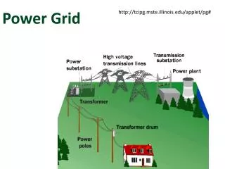
International Journal of Trend in Scientific Research and Development (IJTSRD) @ www.ijtsrd.com eISSN: 2456-6470 converters. Moreover, the important issue in droop control is a static trade-off between voltage regulation and reactive power. Micro grid power system: Power systems currently undergo considerable change in operating requirements mainly as a result of deregulation and due to an increasing amount of distributed energy resources(DER). In many cases, DERs include different technologies that allow generation in small scale(micro sources) and some of them take advantage of renewable energy resources(RES) such as solar, wind or hydro energy. Having micro sources close to the load has the advantage of reducing transmission losses as well as preventing network congestions. Moreover, the possibility of having a power supply interruption of end-customers connected to low voltage (LV) distribution grid (in Europe 230Vandinthe USA110V) is diminished since adjacent micro sources, controllable load sand energy storage systems can operate in the islanded mode in case of severe system disturbances. Technical challenges in Micro grid: The protection system is one of the major challenges for Micro grid which must react to both the main grid and Micro grid faults. The protection system should cut off the Micro grid from the main grid as rapidly as necessary to protect the Micro grid loads for the first case and for the second case the protection system should isolate the smallest part of the Micro grid when clears the fault[30]. A segmentation of Micro grid, i.e. a design of multiple islands or sub- Micro grids must be supported by micro source and load controllers. In these conditions problems related to selectivity (false, unnecessary tripping) and sensitivity (undetected faults or delayed tripping)of protection system may arise. To realize the emerging potential of distributed generation, a system approach i.e. Micro grid is proposed which considers generation and associated loads as a subsystem. This approach involves local control of distributed generation and hence reduces the need for central dispatch. During disturbances by islanding generation and loads, local reliability can be higher in Micro grid than the whole power system. This application makes the system efficiency double. The current implementation of the Micro grid incorporate sources with loads, permits for intentional islanding and use available waste heat of power generation systems. The main objective of this thesis is the development of a hybrid Micro grid which will reduce the process of multiple reverse conversions associated with individual AC and DC grid by the combination of 1.AC and DC sub-grid 2.Photovoltaic(PV) system and 3.Wind turbine generator Islanding: Islanding is the situation in which a distribution system becomes electrically isolated from the remainder of the power system, yet continues to be energized by DG connected to it. As shown in the figure. Traditionally, a distribution system doesn’t have any active power generating source in it and it doesn’t get power in case of a fault in transmission line upstream but with DG, this presumption is no longer valid. Current practice is that almost all utilities require DG to be disconnected from the grid as soon as possible in case of islanding. Issues with Islanding: Although there are some benefits of islanding operation there are some drawbacks as well. Some of them are as follows: ?Line worker safety can be threatened by DG sources feeding a system after primary sources have been opened and tagged out. ?The voltage and frequency may not be maintained within a standard permissible level. Islanded system may be inadequately interconnection. ?Instantaneous reclosing could result in out of phase reclosing of DG. As a result of which large mechanical torques and currents are created that can damage the generators or prime movers [26] Also, transients are created, which are potentially damaging to utility and other customer equipment. Out of phase reclosing, if occurs at a voltage peak, will generate a very severe capacitive switching transient and in a lightly damped system, the crest over-voltage can approach three times rated voltage. METHODOLOGY: In the islanded mode of operation, there is the need to manage reactive power-sharing and allow RESs to work with maximum active power. Hence, the new reactive power sharing algorithm was proposed in this paper, based on the analysis of power-sharing between converters in MG. The novel solution prevents the reactive power circulation and disconnection or damage of any converter in MG. Moreover, it allows to converters operation with MPPT, causing better exploitation of each RES and keeping apparent power of each unit below nominal level as long as possible. Because of the short switching period of power electronics converters in RES, the algorithm was developed for implementation in a hierarchical control structure, providing parallel calculations in each PCU. Simulation analysis was performed, where the three solutions of power control in islanded MG were compared what confirms the correct operation of developed algorithm and shows the advantage of proportional power-sharing over others solution presented in the literature. Photovoltaic system: The photoelectric effect was first noted by French physicist EdmundBecquerelin1839. He proposed that certain materials have the property of producing small amounts of electric current when exposed to sunlight. In1905, Albert Einstein explained the nature of light and the photoelectric effect which has become the basic principle for photovoltaic technology. In 1954 the first photovoltaic module was built by Bell Laboratories. A photovoltaic system makes use of one or more solar panels to convert solar energy into electricity. Photovoltaic cell: The basic ingredients of PV cells are semiconductor materials, such as silicon. For solar cells, a thin semiconductor wafer creates an electric field, on one side positive and negative on the other. grounded by the DG @ IJTSRD | Unique Paper ID – IJTSRD26498 | Volume – 3 | Issue – 5 | July - August 2019 Page 886
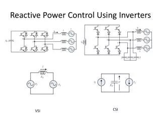
International Journal of Trend in Scientific Research and Development (IJTSRD) @ www.ijtsrd.com eISSN: 2456-6470 in watts) at a certain wind speed (called the rated speed) at standard temperature and altitude. The rated power of small wind turbines falls in the range of 1,000 to 100,000 watts. One thousand watts is one kilowatt (kW). Large wind turbines include all of those turbines over 100 kilowatts. Most larger turbines, however, are rated at one megawatt or higher. A megawatt is a million watts or 1,000 kilowatts. The Advantages of Wind Energy: Although residential wind turbines and their energy source, the wind, have a few downsides, wind energy is an abundant and renewable resource. We won’t run out of the wind for the foreseeable future, unlike oil and natural gas. Small-scale wind energy could also help decrease our reliance on declining and costly supplies of oil — if electricity generated by wind is used to power electric or plug-in electric hybrid cars and trucks, displacing gasoline, which is refined from oil. The wind could even eventually reduce our dependence on nuclear power as well. Droop control: In electricity generation, droop speed control is the primary instantaneous system using net frequency deviations to distribute with stability load changes over generating plants. Droop control allows individual generators to share electric system load changes in proportion to their maximum power rating. For stable operation of the electrical grid of North America, power plants typically operate with a four or five percent speed droop.[1][citation needed] With 5% droop the full-load speed is 100% and the no-load speed is 105%. This is required for the stable operation of the net without hunting and dropouts of power plants. Normally the changes in speed are minor due to the inertia of the total rotating mass of all generators and motors running in the net.[2] Adjustments in power output are made by slowly raising the droop curve by increasing the spring pressure on a centrifugal governor or by an engine control unit adjustment. Generally, this is a basic system requirement for all power plants because the older and newer plants have to be compatible in response to the instantaneous changes in frequency without depending on outside communication. Power Electronic Converters: Power electronic circuits in the wind and photovoltaic (PV) power systems basically perform the following functions: Convert alternating current (AC) to direct current (DC) ?Convert DC to AC ?Control voltage ?Control frequency ?Control frequency Insulated Gate Bipolar Transistor (IGBT): IGBT has been developed by combining into it the best qualities of both BJT and PMOSFET. Thus an IGBT possesses high input impedance like a PMOSFET and has low on-state power loss as in a BJT. Further, IGBT is free from second breakdown problem present in BJT. All these merits have made IGBT very popular amongst power-electronics engineers. IGBT is also known as metal oxide insulated gate transistor (MOSIGT), conductively-modulated field-effect transistor (COMFORT) or gain-modulated FET(GEMFET). It was also initially called insulated gate transistor (IGT). Fig: Basic structure of PV cell Photovoltaic module: Because of the low voltage generation in a PV cell(around 0.5V), several PV cells are connected in series(for high voltage) and in parallel(for high current) to form a PV module for the desired output. In case of partial or total shading, and at night there may be a requirement of separated io destroy void reverse currents Thep- njunctionsofmono-crystalline silicon cells may have adequate ever-current characteristics and the necessary. There is wastage of power because of reverse current switch directs too overheating of shaded cells. At higher temperatures solar cells provide less efficiency and installers aim to offer good ventilation behind the solar panel. Working of PV cell: The basic principle behind the operation of a PV cell is a photoelectric effect. In this effect, the electron gets selected from the conduction band as a result of the absorption of sunlight to a certain wavelength by the matter (metallic or on-metallic solids, liquids or gases). So, in a photovoltaic cell, when sunlight surface, some portion of the solar energy is in the semiconductor material. WIND ENERGY SYSTEM: Utilization 0f Wind Power: Wind turbines are commonly described in terms of rated power, also known as rated output or rated capacity. Rated power is the instantaneous output of the turbine (measured @ IJTSRD | Unique Paper ID – IJTSRD26498 | Volume – 3 | Issue – 5 | July - August 2019 Page 887
International Journal of Trend in Scientific Research and Development (IJTSRD) @ www.ijtsrd.com eISSN: 2456-6470 Basic Structure Fig illustrates the basic structure of an IGBT. It is constructed virtually in the same manner as a power MOSFET. There is, however, a major difference in the substrate. The n+ layer substrate at the drain in a PMOSFET is now substituted in the IGBT by a p+ layer substrate called collector C. Like a power MOSFET, an IGBT has also thousands of basic structure cell connected approximately on a single chip of silicon. Proportional Reactive Power Sharing: In order to manage reactive power in islanded AC Micro grid, the instantaneous active power and nominal apparent power of each converter have to be taking into consideration. Based on Frieze power theory, that power can be represented by orthogonal vectors, which lengths are active and reactive power and their vector sum is equal to the apparent power. Simulation Circuit and Results: Figure: N-Channel IGBT Cross Section Working: When the collector is made positive with respect to the emitter, IGBT gets forward biased. With no voltage between gate and emitter, two junctions between n- region and p region (i.e. junction J2) are reversed biased; so no current flows from collector to emitter When gate is made positive with respect to emitter by voltage VG, with gate-emitter voltage more than the threshold voltage VGET of IGBT, an n- channel or inversion layer, is formed in the upper part of p region just beneath the gate, as in PMOSFET. PI controller: Methods of Tuning PI-Controllers: Simulation Results: There are various conventional methods used for tuning of PI-controller such as : 1.Trial and error 2.Continuous cycling method (Ziegler Nichols method) 3.Process Reaction Curve Methods (Ziegler-Nichols and Cohen-Coon methods) 4.Ziegler-Nichols method (both types of responses) 5.Cohen-Coon method (self-regulating response only Trial and error: It is quite time-consuming if a large number of the trial are required or if the process dynamics are slow. Testing can be expensive because of lost productivity or poor product quality Continuous cycling may be objectionable because the process is pushed to the stability limit. @ IJTSRD | Unique Paper ID – IJTSRD26498 | Volume – 3 | Issue – 5 | July - August 2019 Page 888
International Journal of Trend in Scientific Research and Development (IJTSRD) @ www.ijtsrd.com eISSN: 2456-6470 keeping apparent power of each unit below nominal level as long as possible. References: [1]Y. Xinghuo, C. Cecati, T. Dillon, and M. G. Simões, “The new frontier of smart grids,” IEEE Ind. Electron. Mag., vol. 5, no. 3, pp. 49–63, Sep. 2011. [2]F. Blaabjerg and J. M. Guerrero, “Smart grid and renewable energy systems,” in Proc. Int. Conf. Elect. Mach. Syst. (ICEMS), Beijing, China, 2011, pp. 1–10. [3]European photovoltaic industry association. (May 2012). Global Market Outlook for Photovoltaics until 2016. [Online]. http://www.epia.org/fileadmin/user_upload/Publicati ons/ Global-Market-Outlook-2016.pdf Available: [4]Renewable energy policy network for the 21st century. Renewables 2011 Global Status Report. [Online]. Available: http://www.ren21.net/REN21Activities/Publications/ GlobalStatusReport/ GSR2011/tabid/56142/Default.aspx [5]Global wind energy council. Global Wind Report: Annual Market Update 2011. http://gwec.net/ content/uploads/2012/06/Annual_report_2011_lowre s.pdf [Online]. Available: wp- [6]The European wind energy association. (Feb. 2013). Wind in Power, 2012 European Statistics. [Online]. Available: http://www.ewea.org/ admin/files/library/publications/statistics/Wind_in_p ower_annual_ statistics_2012.pdf file [7]The European wind energy association. (Feb. 2012). Wind in Power, 2011 European Statistics. [Online]. Available: http://www.ewea.org/ admin/files/library/publications/statistics/Wind_in_p ower_2011_ European_statistics.pdf file Conclusion: The Micro grid is the advance system for RES integration with own control structure. Usually, the Hierarchical Control is implemented with Droop Control at primary level. In the islanded mode of operation, there is the need to manage reactive power-sharing and allow RESs to work with maximum active power. Hence, the new reactive power sharing algorithm was proposed in this paper, based on the analysis of power-sharing between converters in the Micro grid. The novel solution prevents the reactive power circulation and disconnection or damage of any converter in the Micro grid. Moreover, it allows to converters operation with MPPT, causing better exploitation of each RES and [8]ZPRYME and IEEE smart grid. (Nov. 2012). Power Systems of the Future: The Case for Energy Storage, Distributed Generation and Micro grids. [Online]. Available: http://www.admu.edu.ph/sites/default/ files/zprymepowersystems.pdf [9]Guide for Design, Operation, and Integration of Distributed Resource Island Systems with Electric Power Systems, IEEE Standard 1547.4, 2011. [10]Engler and N. Soultanis, “Droop control in LV-grids,” in Proc. Int. Conf. Future Power Syst., Amsterdam, The Netherlands, 2005, pp. 1–6. @ IJTSRD | Unique Paper ID – IJTSRD26498 | Volume – 3 | Issue – 5 | July - August 2019 Page 889