Download
1 / 6
60 likes | 70 Vues
Power transmission and distribution systems are designed for operation with sinusoidal voltage and current waveform in constant frequency. Power electronic control devices due to their inherent non linearity draw harmonic and reactive power form the supply mains. The wide use power electronic equipment with linear load causes an increasing harmonics distortion in the ac mains currents. Harmonics component is a very serious and harmful problem in the distribution system. The main adverse effects of harmonic current and voltage on power system equipment are overheating, overloading, perturbation of sensitive control and electronic equipment, capacitor failure, communication interferences, process problem, motor vibration, resonances problem and low power factor. This paper describes the modelling of active filter with synchronous d q reference frame theory for harmonic compensation in distribution systems. The case study is carried out at Hlaingtharyar township distribution system. The model is implemented for harmonic analysis from simulation using a Matlab Simulink with the THD values obtained by practical measurement. Khine Zar Maw "Design of Active Filter for Reducing Harmonic Distortion in Distribution Network" Published in International Journal of Trend in Scientific Research and Development (ijtsrd), ISSN: 2456-6470, Volume-3 | Issue-5 , August 2019, URL: https://www.ijtsrd.com/papers/ijtsrd26663.pdf Paper URL: https://www.ijtsrd.com/engineering/electrical-engineering/26663/design-of-active-filter-for-reducing-harmonic-distortion-in-distribution-network/khine-zar-maw<br>

E N D
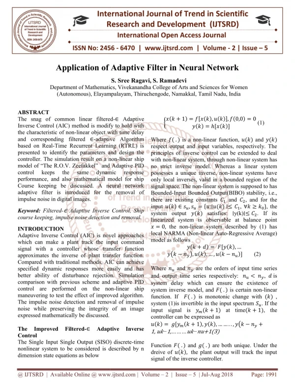
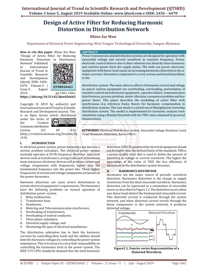
International Journal of Trend in Scientific Research and Development (IJTSRD) Volume 3 Issue 5, August 2019 Available Online: www.ijtsrd.com e-ISSN: 2456 – 6470 Design of Active Filter for Reducing Harmonic Distortion in Distribution Network Khine Zar Maw Department of Electrical Power Engineering, West Yangon Technological University, Yangon, Myanmar How to cite this paper: Khine Zar Maw "Design of Active Filter for Reducing Harmonic Distortion in Distribution Network" Published in International Journal of Trend in Scientific Research and Development (ijtsrd), ISSN: 2456- 6470, Volume-3 | Issue-5, August 2019, https://doi.org/10.31142/ijtsrd26663 Copyright © 2019 by author(s) and International Journal of Trend in Scientific Research and Development Journal. This is an Open Access article distributed under the terms of the Creative Commons Attribution License (CC (http://creativecommons.org/licenses/by /4.0) I. INTRODUCTION In electrical power system, power harmonics has become a serious problem nowadays. The electrical power system normally operates at 50 Hz frequency. However, saturated devices such as transformers, arcing loads such as florescent lamp and power electronic devices will produce current and voltage components with frequencies higher than the fundamental frequency into the power line. These higher frequencies of current and voltage components are known as the power harmonics. Harmonic distortion can cause severe disturbances to certain electrical equipment’s requirements. The harmonics have the following problems on normal operation of distribution power system. 1.Relay malfunction, 2.Transformer hum, 3.Shutdowns, 4.Metering and Telecommunication interference, 5.Overheating of transformers, 6.Overloading of neutral conductor, 7.Three phase unbalance, 8.Distorted supply voltage, and 9.Shortening life span of electrical installations. The distribution substation has to limit the harmonic currents by controlling their loads and the utilities should limit the harmonic voltages by controlling the power system impedances. This is to ensure to carry their responsibility on controlling the harmonics level in the power system. The IEEE 519-1992 standards demand that the total harmonic ABSTRACT Power transmission and distribution systems aredesigned for operation with sinusoidal voltage and current waveform in constant frequency. Power electronic control devices due to their inherent non linearity draw harmonic and reactive power form the supply mains. The wide use power electronic equipment with linear load causes an increasing harmonics distortion in the ac mains currents. Harmonics component is a very serious and harmful problem in the distribution system. The main adverse effects of harmonic current and voltage on power system equipment are overheating, overloading, perturbation of sensitive control and electronic equipment, capacitor failure, communication interferences, process problem, motor vibration, resonances problem and low power factor. This paper describes the modelling of active filter with synchronous d-q reference frame theory for harmonic compensation in distribution systems. The case study is carried out at Hlaingtharyar township distribution system. The model is implemented for harmonic analysis from simulation using a Matlab/Simulink with the THD values obtained by practical measurement. KEYWORDS: Electrical Distribution System, Sinusoidal voltage Nonlinear Load, Total Harmonic Distortion, Active Filters IJTSRD26663 pp.1461-1466, BY 4.0) distortion (THD %) produced by electrical equipment should not be higher than the defined limits of the standards. THD is a power quality term that is used to define the amount of distortion in voltage or current waveform .The higher the percentage of the value of THD, the less efficiency of equipment in the distribution system becomes. II. HARMONICS DISTORTION Harmonics are the major source of periodic waveform distortion. Harmonics distortion is the change in supply waveforms from the ideal sinusoidal waveform. Harmonics distortion can be expressed as a summation of sinusoidal waves as described in Figure 2.1. The distortion occurs when non-linear loads distort the fundamental sinusoidal current. This distorted current is conducted through the system network, and when distorted current travels through the linear components in the system network, it produces distorted voltage. Figure2.1. Fourier series Representation of a Distorted Waveform @ IJTSRD | Unique Paper ID – IJTSRD26663 | Volume – 3 | Issue – 5 | July - August 2019 Page 1461
International Journal of Trend in Scientific Research and Development (IJTSRD) @ www.ijtsrd.com eISSN: 2456-6470 Current harmonics affect the distribution system by loading the system when the waveforms of other frequencies use the same system capacity without contributing any power to the load. They also increase the system copper losses. However, current harmonics cannot affect directly the linear loads in the system but the non-linear loads that cause current harmonics are affected. On the other hand, voltage harmonics affect the entire system, not just the non-linear loads, and their impact depends on the distance between the power source and the harmonics-causing. III. HARMONIC POLLUTION INDICES The total harmonic distortion (THD) is the most common measurement indices of harmonic distortion. THD applies to both current and voltage and is defined as the root mean- square (rms) value of harmonics divided by the rms value of the fundamental, and then multiplied by 100% as shown in the following equation: To provide a reference guide for both utilities and their customers, many international standards have been proposed, such as IEEE-519 and IEC 61000-4-7. According to these standards, harmonics pollution should not exceed certain limits. These limits have been specified using harmonics indices. Total harmonics distortions (THD) are the most widely used harmonics indices. A.Total Harmonics Distortion (THD) According to IEEE-519 standards, total harmonics distortion is defined as the summation of the effective value of the harmonics components in the distorted waveform relative to the fundamental component. It can be calculated for either voltage or current. IV. Any combination of passive (R, L, C) and active (transistors, op-amps) elements designed to select or reject a band of frequencies is called a filter. Filters are used to filter out any unwanted frequencies due to nonlinear characteristics of some electronic devices or signals picked up by the surrounding medium. Filters are one of those corrective (remedial) solutions aimed at overcoming harmonic problems and to keep them within safe limits. To reduce the harmonics conventionally passive L–C filters were used and also capacitors were employed to improve the power factor of the ac loads. But the passive filters have several drawbacks like fixed compensation, large size and resonance problem. To mitigate the harmonics problem, many research work developments are developed on the active power (APF) filters or active power line conditioners [10].The active power filter (APF) is a popular approach for cancelling the harmonics in power system. The main component in the APF is the control unit. To cancel the harmonics and compensate the reactive power APF is the suitable solution. The APF concept is to use an inverter to inject currents or voltages harmonic components to cancel the load harmonic components. The more usual configuration is a shunt APF to inject current harmonics into the point of common coupling (PCC). The APF can be installed in a low voltage power system to compensate one or more loads; thus, it avoids the propagation of current harmonics in the system. The developments of different control strategies give APF to a new location. As APF compensate the reactive power and cancel the harmonics, it is also called as active power line conditioners (APLC). The operation of APF depends on algorithm to controller. A.Synchronous reference frame method Synchronous reference frame method is based on the transformation of vectors into synchronously rotating direct (d), and quadrature axis (q) reference frames. The following Figure 3.6 shows the principal of Synchronous reference theory based control in active filter. HARMONIC MITIGATING TECHNIQUES [1] where, Vh = the RMS value of voltage harmonics component h, Ih = the RMS value of current harmonics component h; The THD for current is as follows: THD of current varies from a few percent to more than 100%. THD of voltage is usually less than 5%. Voltage THDs below 5% are widely considered to be acceptable, while values above 10% are definitely unacceptable and cause the problems for sensitive equipment and loads [8]. The main problem of harmonics is voltage waveform distortion by calculation the relation between the fundamental and distorted waveforms by finding the square root of the sum of the square of all harmonics generated by a single load, and then dividing this number by the nominal 50 Hz waveform value. Most international standards use these indices to determine the total acceptable harmonics distortion limit and the individual harmonics distortion ratio for each effective harmonic; both individual and total harmonics distortion measurements should be within the standard limits ∞ ∑ = 2 h I [2] h 2 = × THDi 100% I 1 Figure4.1. Principal of Synchronous Reference Theory Based Control Among them, Filters may reduce harmonic levels to below IEEE 519-1992 guidelines. recommendations that are the Total voltage distortion (THD) is 5.0% and the total current distortion level is 4% in distribution system. The harmonic limit @ IJTSRD | Unique Paper ID – IJTSRD26663 | Volume – 3 | Issue – 5 | July - August 2019 Page 1462
International Journal of Trend in Scientific Research and Development (IJTSRD) @ www.ijtsrd.com eISSN: 2456-6470 V. The distribution system under study is shown in fig (5.1). The detailed study is carried out at Hlaingtharyar distribution substation No (1). CASE STUDY Fig.5.1 [a] Sinle Line Diagram of No 1. Transformer in Hlaingtharyar Substation (1) Fig.5.1 [b] Single Line Diagram Of No 2. Transformer In Hlaingtharyar Substation (1) The substation is located at Hlaingtharyar Township, Yangon, Myanmar. This substation is constructed for supplying the electric power to Hlaingtharyar industrial zone and some housing of Hlaingtharyar. Hlaingtharyar Industrial Zone is the largest one in Myanmar. Since the dominant load of this substation is industrial load. The incoming line of substation No (1) is taken from 33 kV bus of Hlaingtharyar Primary substation which is located at west of Hlaingtharyar township. Substation No (1) comprise two number of 20 MVA, 33 kV/ 11 kV transformers. There are eight number of 11 kV main distribution feeder which are connected to two separate 11kV bus bar of substation No (1) as shown in Figure (5.1). The different types of linear and non- linear loads are connected to the system. The Figure 5.1 is showing the single line diagram of Hlaingtharyar substation (1). The following table are showing the total voltage and current harmonic distortion levels in Hlaingtharyar substation (1). Table 5.1. Voltage and Current Distortion in Hlaingtharyar Distribution Networks Harmonic orders h=5 h=7 h=11 h=13 TOTAL HARMONIC DISTORTION (%) THDV 8.69 3.72 3.50 THDi 3.9 1.19 0.71 2.72 0.47 10.68 4.17 @ IJTSRD | Unique Paper ID – IJTSRD26663 | Volume – 3 | Issue – 5 | July - August 2019 Page 1463
International Journal of Trend in Scientific Research and Development (IJTSRD) @ www.ijtsrd.com eISSN: 2456-6470 The results show that the harmonic distortion exceeds the permissible limits for voltage and current in PCC. The more salient orders are the 5th, 7th, 11th and 13th harmonic orders. The simulation waveform without filter in pcc is shown in figure5. 2. Fig.5.2. Simulation Waveform Results Without Filter In PCC THE DISTRIBUTION SYSTEM WITH ACTIVE FILTER The mitigation method is active filter based on d-q methods for maintaining sinusoidal source currents when the source supplying a non-linear load. And then, they are installed at the PCC in the Hlaing Tharyar substation (1). The complete model of active power filter is presented in Figure 6.1 and results were obtained by using MATLAB/Simulink Sim power system Toolbox software for a APF compensating harmonics produced by Non-linear loads. A.Calculation for capacitance and reactance of active filter The reactive power demand of the system without harmonic filter is 10.99 MVAR. QC supply by filter = 0.3× 10.99 = 3.3 MVAR. VI. 2 2 V 5000 = = = Ω X . 7 576 C 6 × Q 3 . 3 10 C For PWM generator, the switching frequency is set as 1080 Hz. Thus the required capacitance is obtained as follows: 1 X f 2π C . π × × × 40 % ripple of Iout, inductor size is obtained as follows; 5k 5k) - 19.05k ( L = × × × Thus, 7 mH inductor is selected for active filter. B.Synchronous Method Active Filter using d-q-0 Theory For PI controller, the values of Kp and Ki are chosen and these are shown as follows: Kp = 0.0016 Ki = 0.00015 1 − 5 = = = × ≈ C 1 945 . 10 F 20 F µ 2 1080 7 576 × = 6.94mH 19.05k 1080 (0.4 1230.4) Figure6.1. Simulink Diagram of Synchronous Method Active Filter using d-q-0 Theory @ IJTSRD | Unique Paper ID – IJTSRD26663 | Volume – 3 | Issue – 5 | July - August 2019 Page 1464
International Journal of Trend in Scientific Research and Development (IJTSRD) @ www.ijtsrd.com eISSN: 2456-6470 VII. CASE STUDY Fig.7.1. Modelling of Hlaing Tharyar Substation (1) with Active filters The following Table 7.1 is showing the total harmonic voltage and current distortion with filters. Table7.1. Voltage and Current Distortion in Hlaingtharyar Distribution Network Harmonic orders THDv 0.24 0.15 THDi 0.19 0.08 After installing the active filters, the THD % of voltage and current are changed and declined in HTY network. The THDv% is 0.91% and THDi% is 0.26% at PCC in HTY network. 4 5000 4500 4000 3500 3000 2500 2000 h=5 h=7 h=11 h=13 Total 1500 1000 500 0.14 0.05 0.09 0.03 0.91 0.26 0 0 0.2 0.4 0.6 0.8 1 1.2 1.4 1.6 1.8 2 Figure7.3. DC Voltage with Active Filter for Case Study In simulation result, the dc voltage is reached the steady state at 1.5 sec when the Kp is 0.0016 and Ki is 0.00015 for PI controller. Table7.2. Total Harmonic Distortion Without and With Filters in HTY Substation (1) System without mitigation techniques (%) THDv % 10.68 THDi % 4.17 According the Table 7.2, the active filter is more effective compensation of harmonics in this network. The percentage of total harmonic voltage distortion with active filter is reduced to 0.91% and current is reduced to 0.26 % which are very lower than the harmonics limit 5% imposed by the IEEE standard. x 10 3 2 System System with active filter V 1 0 0.91 0.26 600 400 I 200 0 0.4 0.5 0.6 0.7 0.8 0.9 1 1.1 1.2 1.3 Time (sec) Figure 7.2.Three Phase RMS Voltage and Current Waveforms with Active Filter @ IJTSRD | Unique Paper ID – IJTSRD26663 | Volume – 3 | Issue – 5 | July - August 2019 Page 1465
International Journal of Trend in Scientific Research and Development (IJTSRD) @ www.ijtsrd.com eISSN: 2456-6470 VIII. Under Substation (1) distribution network is increasing the non-linear loads, distorted voltage and current are cause to be harmonics. That can be effected power system quality and reduced the power system performance. The control or mitigation of the power quality problems may be realized to use mitigation techniques applied in distribution system. The mitigation technique is active filtering method that may reduce harmonic levels to below IEEE 519 guidelines. IX. CONCLUSIONS The harmonic level has a great effect on the performance of the system components and equipment’s. Harmonic analysis for the distribution system is necessary for appreciating system operation and upgrade. In Hlaingtharyar Substation (1) has the voltage distortion level is 10.68% and current distortion is 4.17% according to measure without filters. After installing filters, the voltage distortion will be 0.19% and current distortion is 0.26%. The results of THD are significantly decline in Hlaingtharyar Substation. DICUSSIONS ACKNOWLEDGMENTS The author wishes to express her deepest gratitude to her dear parents for their support, help and giving suggestions. Similar thanks to my son and daughter because of my vitamins when I feel tired. REFERENCES [1]J. Arrillaga, D.A. Bradley, and P.S Bodger, Power System Harmonics. New York: John Wiley & Sons, 1985, pp. 5- 135. [2]IEEE Recommended Practices and Requirements for Harmonic Control in Electrical Power Systems”. IEEE Std 519 – 1992. [3]IEEE/CIGRE Joint Task Force on Stability Terms and Definitions, “Definition and Classification of Power System Stability”, IEEE Trans-actions on Power Systems, Vol. 5, No. 2, May 2004, pp. 1387–1401. [4]“IEEE Recommended Practice for Electric Power Distribution for Industrial Plants”, IEEE Std 141-1993 (Revision of IEEE Std 141-1986 @ IJTSRD | Unique Paper ID – IJTSRD26663 | Volume – 3 | Issue – 5 | July - August 2019 Page 1466