Download
1 / 7
70 likes | 79 Vues
NDE has evolved as an essential demand in much modern engineering equipment's like Heat Exchangers, Marine Industries and Oil Refineries. The performance levels and reliability of the NDE is more important to the end use of the object being inspected. Failure is the primary threat to the integrity, safety and performance of marine structure. Duplex Steel 2205 of dimensions 200X170X12 weldments are chosen for this project in view of its applications in heat exchangers, marine and oil refineries. It was taken for this project in the form of plate and welded by Tungsten Inert Gas welding TIG . The basic NDT experimental methods such as Liquid Penetrating Test, Magnetic Particle Test, Ultrasonic Test, and Radiography Test are chosen for quality assurance of the materials. Penetrant testing for to surface defects, Ultrasonic testing to detect the subsurface and internal defects, Gamma Ray Radiography for internal defects. The results from methods were analysed. Surface defects were detected by penetrant testing and internal defects like inclusions, blow holes, porosity, lack of penetration were detected by both Radiography testing and Ultrasonic testing. P. Varalakshmi | K. Santhosh Reddy | P. Sruthi | M. Praveena | P. Indu "Evaluation of Tungsten Inclusions in Fusion Welded Duplex Steel by Gamma Ray Radiation" Published in International Journal of Trend in Scientific Research and Development (ijtsrd), ISSN: 2456-6470, Volume-3 | Issue-3 , April 2019, URL: https://www.ijtsrd.com/papers/ijtsrd23179.pdf Paper URL: https://www.ijtsrd.com/engineering/mechanical-engineering/23179/evaluation-of-tungsten-inclusions-in-fusion-welded-duplex-steel-by-gamma-ray-radiation/p-varalakshmi<br>

E N D
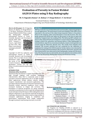
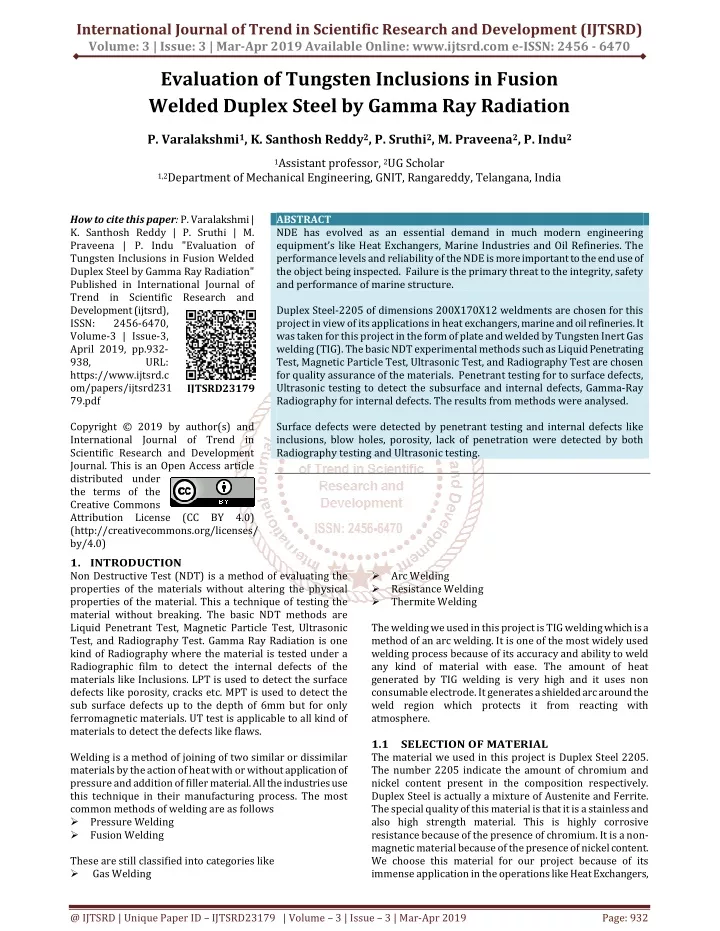
International Journal of Trend in Scientific Research and Development (IJTSRD) Volume: 3 | Issue: 3 | Mar-Apr 2019 Available Online: www.ijtsrd.com e-ISSN: 2456 - 6470 Evaluation of Tungsten Inclusions in Fusion Welded Duplex Steel by Gamma Ray Radiation P. Varalakshmi1, K. Santhosh Reddy2, P. Sruthi2, M. Praveena2, P. Indu2 1Assistant professor, 2UG Scholar 1,2Department of Mechanical Engineering, GNIT, Rangareddy, Telangana, India How to cite this paper: P. Varalakshmi | K. Santhosh Reddy | P. Sruthi | M. Praveena | P. Indu "Evaluation of Tungsten Inclusions in Fusion Welded Duplex Steel by Gamma Ray Radiation" Published in International Journal of Trend in Scientific Research and Development (ijtsrd), ISSN: 2456-6470, Volume-3 | Issue-3, April 2019, pp.932- 938, URL: https://www.ijtsrd.c om/papers/ijtsrd231 79.pdf Copyright © 2019 by author(s) and International Journal of Trend in Scientific Research and Development Journal. This is an Open Access article distributed under the terms of the Creative Commons Attribution License (CC BY 4.0) (http://creativecommons.org/licenses/ by/4.0) 1.INTRODUCTION Non Destructive Test (NDT) is a method of evaluating the properties of the materials without altering the physical properties of the material. This a technique of testing the material without breaking. The basic NDT methods are Liquid Penetrant Test, Magnetic Particle Test, Ultrasonic Test, and Radiography Test. Gamma Ray Radiation is one kind of Radiography where the material is tested under a Radiographic film to detect the internal defects of the materials like Inclusions. LPT is used to detect the surface defects like porosity, cracks etc. MPT is used to detect the sub surface defects up to the depth of 6mm but for only ferromagnetic materials. UT test is applicable to all kind of materials to detect the defects like flaws. Welding is a method of joining of two similar or dissimilar materials by the action of heat with or without application of pressure and addition of filler material. All the industries use this technique in their manufacturing process. The most common methods of welding are as follows ?Pressure Welding ?Fusion Welding These are still classified into categories like ? Gas Welding ABSTRACT NDE has evolved as an essential demand in much modern engineering equipment’s like Heat Exchangers, Marine Industries and Oil Refineries. The performance levels and reliability of the NDE is more important to the end use of the object being inspected. Failure is the primary threat to the integrity, safety and performance of marine structure. Duplex Steel-2205 of dimensions 200X170X12 weldments are chosen for this project in view of its applications in heat exchangers, marine and oil refineries. It was taken for this project in the form of plate and welded by Tungsten Inert Gas welding (TIG). The basic NDT experimental methods such as Liquid Penetrating Test, Magnetic Particle Test, Ultrasonic Test, and Radiography Test are chosen for quality assurance of the materials. Penetrant testing for to surface defects, Ultrasonic testing to detect the subsurface and internal defects, Gamma-Ray Radiography for internal defects. The results from methods were analysed. Surface defects were detected by penetrant testing and internal defects like inclusions, blow holes, porosity, lack of penetration were detected by both Radiography testing and Ultrasonic testing. ?Arc Welding ?Resistance Welding ?Thermite Welding The welding we used in this project is TIG welding which is a method of an arc welding. It is one of the most widely used welding process because of its accuracy and ability to weld any kind of material with ease. The amount of heat generated by TIG welding is very high and it uses non consumable electrode. It generates a shielded arc around the weld region which protects it from reacting with atmosphere. 1.1 SELECTION OF MATERIAL The material we used in this project is Duplex Steel 2205. The number 2205 indicate the amount of chromium and nickel content present in the composition respectively. Duplex Steel is actually a mixture of Austenite and Ferrite. The special quality of this material is that it is a stainless and also high strength material. This is highly corrosive resistance because of the presence of chromium. It is a non- magnetic material because of the presence of nickel content. We choose this material for our project because of its immense application in the operations like Heat Exchangers, IJTSRD23179 @ IJTSRD | Unique Paper ID – IJTSRD23179 | Volume – 3 | Issue – 3 | Mar-Apr 2019 Page: 932
International Journal of Trend in Scientific Research and Development (IJTSRD) @ www.ijtsrd.com eISSN: 2456-6470 Oil Refineries, and Boilers etc. As we know the temperature for those applications is very high we need to suggest the best method of suggesting the welding and kind of defects that can arise by using NDT technique. 2.EXPEREMENTAL WORK The material Duplex Steel 2205 of required dimensions i.e. 200x170x12mm is joined by TIG welding in which filler rod used is 2209 and electrode used is Tungsten electrode. The welding type is V-groove butt joint. The chemical composition of duplex steel in percentages are C – 0.3, Cr – 21-23, Ni – 5-6, Si – 1, Mn – 2. After the sample is prepared it is taken for testing for any presence of defects like surface defects, internal defects. The dimensions of the material sample after welding are ?Length = 200mm ?Width = 170mm ?Thickness = 12mm A.Cleaning The surface of the sample is to be cleaned thoroughly with solvents like water and allow it to dry to make it free from dust and oil. The surface cleaning is required to achieve successful readings. Then the penetrants are applied on the surface of the body. These are of two types like water based penetrants called as hydrophilic and lipophilic which is oil based penetrant. Fig 2:PT Spray Cans B.Penetrant Application After the material is cleaned, apply water based or alcohol based penetrant of your choice. Penetrant should be applied evenly for easy detection of defects. Fig 3: Penetrant Application a) Welded Duplex Steel C.Dwell Time Dwell time of about 10 minutes is given for allowing the penetrant to get into the material. D.Excess Removal of Penetrant After allowing the penetrant to get into the material, excess of penetrant is removed by using water and universal cleaner and inspected under UV light. E.Applying Developer Developer is applied evenly on the sample at a distance of 45mm and keeping the sample at 15 deg. The developer used is Non Aqueous Type1 (Solvent Based) b) V-Groove Weld Fig 1: Duplex Steel and Weld Region 2.1 The basic principle of penetrant testing is Capillary Action Penetrant Testing is done to test the surface defects or flaws like weld cracks, porosity, blow holes. The testing procedure is as follows A.Pre Cleaning B.Penetrant Application C.Dwell Time D.Excess Penetrant Removal E.Developer Application F.Developing Time G.Inspection Under Ultralight PENETRANT TEST Fig 4: Developer Application F.Developing Time After the developer is applied on the material, due to the capillary action at the place of defects the penetrant will come out of the surface indicating the defects. @ IJTSRD | Unique Paper ID - IJTSRD23179 | Volume – 3 | Issue – 3 | Mar-Apr 2019 Page: 933
International Journal of Trend in Scientific Research and Development (IJTSRD) @ www.ijtsrd.com eISSN: 2456-6470 G.Inspection The defects are then inspected under UV light. The defects we observed under UV light are Blow Holes, which are minute to consider and at a distance of 45*92mm from top right. b) V2 block Fig 6:Calibration blocks Fig 5: UV Inspection 2.2 The principle of Ultrasonic Testing is Acoustic Impedance Mismatch Ultrasonic Testing is applicable for all materials. In this testing, high frequency sound is transmitted in the material and is reflected back to the probe and displayed on the flaw detector. The principle of sound is Piezoelectric Effect which means conversion of mechanical vibrations into electrical signals and vice versa. Calibration First the flaw detector is calibrated to a known value by using horizontal and angular blocks also known as V1 and V2 blocks respectively. Types of probes used are Normal probe, TR probe and angular probe and the equipment used is Da Vinci Flaw Detector, then calibration of normal probe and angular probe is done. ULTRASONIC TESTING Fig 7:Da Vinci Flaw Detector Construction of DAC Curve The DAC curve constructed with respect to the reference standard having same composition to the test sample. The probe is moved on the surface of the reference block the side drill hole gives an echo. Fig 8: DAC Curve Acceptance Criteria 0 to 20% - Accept 20 to 50% - Note down the reading 50 to 100% - Interpretation >100% - Reject Determination of DAC curve Distance amplitude correction curve ? = 60 S.da = tn/cos?; Sound path = tn*tan? Table 1: Determination of DAC Curve Actual sound path distance distance 17.25 20 14.93 a)V1 block Cal. Sound path 17.32 Cal. Surface Actual surface S. No Thickness (tn) Actual depth Reference dB Scan dB Amplitude (Echo %) 1 10 8.62 48.8 54.8 80 2 20 17.66 34.64 35.34 40 30.6 48.7 54.7 51 3 30 27.63 51.96 55.28 60 47.87 52.5 58.5 45 @ IJTSRD | Unique Paper ID - IJTSRD23179 | Volume – 3 | Issue – 3 | Mar-Apr 2019 Page: 934
International Journal of Trend in Scientific Research and Development (IJTSRD) @ www.ijtsrd.com eISSN: 2456-6470 Inspection The cleaned welded samples are scanned by the calibrated UT machine. The scanning is done by the layer of three skips at 1/2V, 1V, and one and half V sound path according to machined displayed values. The defects amplitude peaks are freezed and recorded as soft copy. a)Normal Probe Fig 10:Schematic of Radiography 2.3.1 Gamma-rays films for general radiography consist of an emulsion-gelatine containing a radiation sensitive silver halide and a flexible, transparent, blue-tined base. The emulsion is different from those used in other types of photography films to account for the distinct characteristics of gamma rays and x-rays, but X-ray films are sensitive to light. Usually, the emulsion is coated on both sides of the base in layers about 0.0005 inch thick. Putting emulsion on both sides of the base doubles the amount of radiation- sensitive silver halide, and thus increases the film speed. The emulsion layers are thin enough so developing, fixing, and drying can be accomplished in a reasonable time. A few of the films used for radiography only have emulsion on one side which produces the greatest detail in the image. When x-rays, gamma rays or light strike the grains of the sensitive silver halide in the emulsion a change takes place in the physical structure of the grains. This change is of such a nature that it cannot be detected by ordinary physical methods. The procedure followed in Radiography is as follows Film D4 film was selected for Gamma-ray radiography followed by placing between the two metallic foil screens; these are inserted into film cassette. Cassette was placed a side. Equipment arrangement: The Gamma-Ray Voltage and current parameters are selected as 120Kv and 3mA respectively SFD and exposer time are calculated by the following formulae’s SFD = t (1+ (f/Ug)) The Penetrameter placed in the sample and the film was placed under the sample The sample is placed with distance of 15.1cm from the Gamma-Ray source The power is switched on and the Gamma-Rays are exposed on the sample with 3sec calculated time after the exposure time the cassette is taken into the dark room. Radiographic Film b) Angular Probe Fig 9: Detection of Defects by Normal and Angular Probes 2.3 Radiography is based on the principle that radiation is absorbed and scattered as it passes through an object. Gamma-rays are invisible electromagnetic radiation of very short wavelength, which will travel in straight lines and imparts highest photon energy. Natural source of gamma rays originating on earth are mostly as a result of radioactive decay and secondary radiation from atmospheric interactions with cosmic ray particles. Unlike alpha and beta rays they pass easily through the bodies. Gamma rays are conventionally defined as having photon energies above 100keV. Gamma rays are produced in the disintegration of radioactive atomic nuclei and in the decay of certain subatomic particles. When a nucleus makes a transition from a high-energy level to a lower-energy level, a photonics emitted to carry off the excess energy; nuclear energy-level differences correspond to photon wavelengths in the gamma-ray region. When an unstable atomic nucleus decays into a more stable nucleus (radioactivity), the “daughter” nucleus is sometimes produced in an excited state. The subsequent relaxation of the daughter nucleus to a lower-energy state results in the emission of a gamma-ray photon. RADIOGRAPHY TEST @ IJTSRD | Unique Paper ID - IJTSRD23179 | Volume – 3 | Issue – 3 | Mar-Apr 2019 Page: 935
International Journal of Trend in Scientific Research and Development (IJTSRD) @ www.ijtsrd.com eISSN: 2456-6470 ?Film Processing The film on exposure to the X or gamma radiation a latent image is formed in the x-ray film. The main purpose of film processing is it converts this invisible latent image formed by x-ray or gamma radiation on the film to a visible and permanent image. Film during process in undergoes five stages. ?Developing: creation of visible image by using developer and the developer consisting of four major components metol, hydroquinone and phenidone with react with silver bromide. The ?Stop bath: after developing the image is already existence and remaining process make it permanent the stop bath consist of acetic acid it will gives the density to the film the film is immersed for 5 minutes. ?Fixing: the fixing was consisting of sodium thio sulphate, Na2SO3, boric acid with water these will fix the film. In this bath the film was immersed for 5 minutes ?Washing: the film is washed by the flowing water for 5 to 10 minutes ?Drying: the wet films are dried by blowing a current of hot hair over the film the temperature between 38-40O C. the film come out dry in 1 or 2 minutes ?Interpretation: After developing the film, we can interpret defects by using illuminator. Fig 11: Radiographic Film 3. 3.1 Results of Liquid Penetration Test The Welded Duplex Steel samples were tested by the dye and florescent penetrant methods. A single blow hole was observed at the heat affected zone. The dimensions of the blow hole open to surface ±1mm depth and 2to3mm width and the defect can be repairable. The following sample was recorded as a photo that shown in fig. RESULTS AND DISCUSSIONS Fig 12: LPT Recorded Defect Table 2: LPT Report Liquid Penetrant Test Report Date of the Report:05-03-2019 Maker No: Welding joint: TIG Material Thickness: 12mm Temperature: Room temperature Lighting equipment: UV Light Developer time:5min Length/diameter 2-3mm Report No: 01 Components: Duplex Steel Part No: Procedure used: Penetration Test Type of penetrant: DYE and FLUORESCENT Client: Shape: Rectangle Drying time: 10min Dwell time:10min Examination Results: S.No: 1 Acceptance criteria: It can be accepted Size: 200X170X12 Penetrant time:5min Location 45X92 Evaluation neglegible Type of indication Blow hole 3.2 The welded Duplex Steel samples were tested by ultrasonic testing. There was one inclusion at the weld and some porosity was detected at the welded region which is too small to be considered. The sample can be accepted as the defects found in UT is too small and the values are below the acceptance limit. Results of Ultrasonic Test Report Fig 13: Defectogram of UT @ IJTSRD | Unique Paper ID - IJTSRD23179 | Volume – 3 | Issue – 3 | Mar-Apr 2019 Page: 936
International Journal of Trend in Scientific Research and Development (IJTSRD) @ www.ijtsrd.com eISSN: 2456-6470 Table 3: Ultrasonic Test Report Ultrasonic Test Report ASNT 07-03-2019 Duplex Steel 2205 Smooth 2 Da Vinci Alpha Normal probe Frequency size 4 MHz 2cm (dia) 4 MHz Reference/Identifications Test Date Test Material Surface Condition No of samples Tested Test Equipment Test probe Couplant: oil and grease Test range:100mm Calibration:V1 and V2 Gain: 47.2 dB Observation remarks: Out of two, one sample have defects. The defects are inclusion, porosity which are too small Procedure no: ASNT Section 5 Date: 07-03-2019 Job no: 1, 2. Angle probe Frequency size 2cm (dia) Report no:1 3.3 Results of Radiography Test Sample of Duplex steel 2205 material is tested by using Gamma-Ray radiography. Inclusions, and small porosity were detected from the recorded film as shown in fig. which are minute to be considered and the acceptance criteria of the sample is good. Fig 14: Radiographic Film Report Job No Material Weld Process IQI.ASTM ACC.STD CODE SL No 1 2 WELD SAMPLES METAL 2205 Duplex Steel TIG Thickness : 12 mm 17 WIRE : ASTM SET - B ASME SEC-IX Source : IR 192 Activity: 12Ci Energy 0.4Mov Focal Spot Size : 2.7x0.9mm Pb Screen-Front : 0.1 mm Back : 0.15 mm SFD : 35 cm Exp. Time : 2 min Film : AA400 Density : 2 to 4 Sensitivity : 2-2T Technique : SWSI OBSERVATIONS Tungsten Inclusions Porosity RADIOGRAPHY NO. Plate - 1 Plate - 2 FILM SIZE 25mm 25mm SEGMENT AB AB REMARKS Good Good Table 4: Radiographic Test Report @ IJTSRD | Unique Paper ID - IJTSRD23179 | Volume – 3 | Issue – 3 | Mar-Apr 2019 Page: 937
International Journal of Trend in Scientific Research and Development (IJTSRD) @ www.ijtsrd.com eISSN: 2456-6470 4.CONCLUSIONS After considering all the parameters and methods of Non Destructive Test it is found that the material Duplex Steel 2205 good enough to use in Heat Exchangers. The theoretical properties of the material is approximately near to the practical values which indicates that material is under good condition. TIG welding is most suggested for this application due to its unique applications and properties. The following are the conclusions we can draw from the above experimentations are ?The presence of Nickel made the material non-magnetic so it cannot be corroded easily and makes the material smooth ?The presence of Chromium makes the material corrosive resistance and gives extra strength. The material is its self stainless and due to the composition of ferrite and austenite the material is very hard. ?TIG weld makes the material very tough and the fusion temperature is very high. The Heat Affected Zone in the material when welded by TIG is small which makes the material to give long duration. 5. [1]ASTM handbook volume number 17 “Non-Destructive Evaluation and Quality Control” REFERENCES [2]Ultrasonic Flaw Detection in Metals-banks old field & Revinding-ILIFEE 1962 [3]Ultrasonic Flaw Detection for Technician’s-third edition, June 2004 by S. C. Drury [4]Hand Book of Non Destructive Evaluation-Charles Heller [5]D. Devakumar, D. B Jabaraj, “Research on Tungsten Arc Welding of Stainless steel-an overview”, Int. journal of scientific &engineering Research, volume 5, issue 1 Jan 2014. @ IJTSRD | Unique Paper ID - IJTSRD23179 | Volume – 3 | Issue – 3 | Mar-Apr 2019 Page: 938