Download
1 / 9
90 likes | 91 Vues
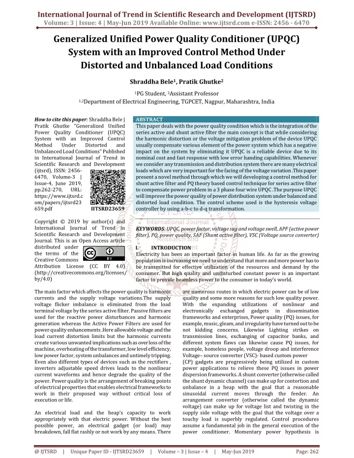
This paper deals with the power quality condition which is the integration of the series active and shunt active filter the main concept is that while considering the harmonic distortion or the voltage mitigation problem of the device UPQC usually compensate various element of the power system which has a negative impact on the system by eliminating it UPQC is a reliable device due to its nominal cost and fast response with low error handing capabilities. Whenever we consider any transmission and distribution system there are many electrical loads which are very important for the facing of the voltage variation .This paper present a novel method through which we will developing a control method for shunt active filter and PQ theory based control technique for series active filter to compensate power problem in a 3 phase four wire UPQC .The purpose UPQC will improve the power quality of power distribution system under balanced and distorted load condition. The control scheme used is the hysteresis voltage controller by using a b c to d q transformation. Shraddha Bele | Pratik Ghutke "Generalized Unified Power Quality Conditioner (UPQC) System with an Improved Control Method Under Distorted and Unbalanced Load Conditions" Published in International Journal of Trend in Scientific Research and Development (ijtsrd), ISSN: 2456-6470, Volume-3 | Issue-4 , June 2019, URL: https://www.ijtsrd.com/papers/ijtsrd23659.pdf Paper URL: https://www.ijtsrd.com/engineering/electrical-engineering/23659/generalized-unified-power-quality-conditioner-upqc-system-with-an-improved-control-method-under-distorted-and-unbalanced-load-conditions/shraddha-bele<br>

E N D
International Journal of Trend in Scientific Research and Development (IJTSRD) Volume: 3 | Issue: 4 | May-Jun 2019 Available Online: www.ijtsrd.com e-ISSN: 2456 - 6470 Generalized Unified Power Quality Conditioner (UPQC) System with an Improved Control Method Under Distorted and Unbalanced Load Conditions Shraddha Bele1, Pratik Ghutke2 1PG Student, 2Assistant Professor 1,2Department of Electrical Engineering, TGPCET, Nagpur, Maharashtra, India How to cite this paper: Shraddha Bele | Pratik Ghutke "Generalized Unified Power Quality Conditioner (UPQC) System with an Improved Control Method Under Unbalanced Load Conditions" Published in International Journal of Trend in Scientific Research and Development (ijtsrd), ISSN: 2456- 6470, Volume-3 | Issue-4, June 2019, pp.262-270, URL: https://www.ijtsrd.c om/papers/ijtsrd23 659.pdf Copyright © 2019 by author(s) and International Journal of Trend in Scientific Research and Development Journal. This is an Open Access article distributed under the terms of the Creative Commons Attribution License (CC BY 4.0) (http://creativecommons.org/licenses/ by/4.0) The main factor which affects the power quality is harmonic currents and the supply voltage variations.The supply voltage flicker imbalance is eliminated from the load terminal voltage by the series active filter. Passive filters are used for the reactive power disturbances and harmonic generation whereas the Active Power Filters are used for power quality enhancements .Here allowable voltage and the load current distortion limits but the harmonic currents create various unwanted implications such as over loss of the machine, overheating of the transformer, low level efficiency, low power factor, system unbalances and untimely tripping. Even also different types of devices such as the rectifiers , inverters adjustable speed drives leads to the nonlinear current waveforms and hence degrade the quality of the power. Power quality is the arrangement of breaking points of electrical properties that enables electrical frameworks to work in their proposed way without critical loss of execution or life. An electrical load and the heap's capacity to work appropriately with that electric power. Without the best possible power, an electrical gadget (or load) may breakdown, fall flat rashly or not work by any means. There ABSTRACT This paper deals with the power quality condition which is the integration of the series active and shunt active filter the main concept is that while considering the harmonic distortion or the voltage mitigation problem of the device UPQC usually compensate various element of the power system which has a negative impact on the system by eliminating it UPQC is a reliable device due to its nominal cost and fast response with low error handing capabilities. Whenever we consider any transmission and distribution system there are many electrical loads which are very important for the facing of the voltage variation .This paper present a novel method through which we will developing a control method for shunt active filter and PQ theory based control technique for series active filter to compensate power problem in a 3 phase four wire UPQC .The purpose UPQC will improve the power quality of power distribution system under balanced and distorted load condition. The control scheme used is the hysteresis voltage controller by using a-b-c to d-q transformation. KEYWORDS: UPQC, power factor, voltage sag and voltage swell, APF (active power filter), PQ, power quality, SAF (Shunt active filter), VSC (Voltage source converter) I. INTRODUCTION Electricity has been an important factor in human life. As far as the growing population is increasing we need to understand that more and more power has to be transmitted for effective utilization of the resources and demand by the consumer. But high quality and undisturbed constant power is an important factor to provide beamless power to the consumer in today’s world. are numerous routes in which electric power can be of low quality and some more reasons for such low quality power. With the expanding utilizations of nonlinear and electronically exchanged frameworks and enterprises, Power quality (PQ) issues, for example, music, gleam, and irregularity have turned out to be not kidding concerns. Likewise Lighting strikes on transmission lines, exchanging of capacitor banks, and different system flaws can likewise cause PQ issues, for example, homeless people, voltage droop and interference Voltage– source converter (VSC)- based custom power (CP) gadgets are progressively being utilized in custom power applications to relieve these PQ issues in power dispersion frameworks. A shunt converter (otherwise called the shunt dynamic channel) can make up for contortion and unbalance in a heap with the goal that a reasonable sinusoidal current moves through the feeder. An arrangement converter (otherwise called the dynamic voltage) can make up for voltage list and twisting in the supply side voltage with the goal that the voltage over a touchy load is superbly regulated. Control procedures assume a fundamental job in the general execution of the power conditioner. Momentary power hypothesis is Distorted and IJTSRD23659 gadgets in dissemination @ IJTSRD | Unique Paper ID - IJTSRD23659 | Volume – 3 | Issue – 4 | May-Jun 2019 Page: 262
International Journal of Trend in Scientific Research and Development (IJTSRD) @ www.ijtsrd.com eISSN: 2456-6470 commonly wanted to create reference signals for the shunt converter. An expanded strategy dependent on momentary responsive power hypothesis in a pivoting reference outline is utilized to smother the music and to address the power factor in. Fluffy rationale is used to control the pay flows of the shunt converter There has likewise been enthusiasm for the circuit topologies of UPQC. UPQC is commonly structured as a three- stage three wire (3P3W) frameworks. The three- stage four- wire framework is likewise acknowledged from the framework where the impartial of arrangement transformer utilized in arrangement part UPQC is considered as the fourth wire for the 3P3W framework. There is likewise single stage UPQC framework. Different topologies, for example, H-connect converters, and single-stage UPQC with three legs are analyzed for the UPQC applications. In development, an UPQC is like a bound together power stream controller (UPFC) [5]. Both UPQC and UPFC utilize two voltage source inverters (VSIs) that are associated with a typical dc vitality stockpiling component. An UPFC is utilized in power transmission framework though UPQC is utilized in a power dispersion framework, to play out the shunt and arrangement remuneration at the same time. In any case, an UPFC just needs to give balance shunt and additionally arrangement pay, since a power transmission framework for the most part works under a decent and bending free condition. Then again, a power conveyance framework may contain dc parts, bending, and unbalance both in voltages and flows. In this manner, an UPQC ought to work under this condition while performing shunt or potentially arrangement pay. The fundamental motivation behind an UPQC is to make up for supply voltage control quality issues, for example, droops, swells, unbalance, gleam, sounds, and for load current power quality issues, for example, sounds, unbalance, receptive current, and nonpartisan current. Fig. 1 demonstrates a solitary line portrayal of the UPQC framework arrangement. The key parts of this framework are as pursues. 1.Two inverters—one associated over the heap which acts as a shunt APF and other associated in arrangement with the line as that of arrangement APF. 2.Shunt coupling inductor LSh is utilized to interface the shunt inverter to the system. It also helps in making the current wave shape smooth. Now and again a detachment transformer is used to electrically disengage the inverter from the organize 3.A typical dc connect that can be framed by utilizing a capacitor or then again an inductor. The dc connect is acknowledged utilizing a capacitor which interconnects the two inverters and likewise keeps up a consistent self-supporting dc transport voltage crosswise over it. 4.A LC channel that fills in as an aloof low-pass channel (LPF) what's more, dispenses with high-recurrence exchanging swells on produced inverter yield voltage. 5.Series infusion transformer that is utilized to associate the arrangement inverter in the system. A reasonable turn proportion is frequently considered to decrease the current or voltage rating of the arrangement inverter. On a basic level, UPQC is a mix of shunt and arrangement APFs with a typical self-supporting dc transport. The shunt inverter in UPQC is controlled in current control mode to such an extent that it conveys a present which is equivalent to the set estimation of the reference current as represented by the UPQC control calculation. Furthermore, the shunt inverter assumes a vital job in accomplishing required execution from an UPQC framework by keeping up the dc transport voltage at a set reference esteem. So as to drop the music created by a nonlinear load, the shunt inverter ought to infuse a current as represented by following condition: iSh(ωt) = I * S (ωt) − iL (ωt) (1) where iSh(ωt), i*S (ωt), and iL (ωt) speak to the shunt inverter current, reference source current, and load current, separately. So also, the arrangement inverter of UPQC is controlled in voltage control mode with the end goal that it creates a voltage and infuses in arrangement with line to accomplish a sinusoidal, free from twisting and at the ideal extent voltage at the heap terminal. The essential activity of an arrangement inverter of UPQC can be spoken to by the accompanying condition: vSr(ωt) = v*L (ωt) − vS (ωt) (2) where vSr(ωt), v*L (ωt), and vS (ωt) Speak to the arrangement inverter infused voltage, reference stack voltage, and real source voltage, individually. On account of a voltage list condition, vSr will speak to the contrast between the reference stack voltage and decreased supply voltage, i.e., the infused voltage by the arrangement inverter to keep up voltage at the heap terminal at reference esteem. In all the reference papers on UPQC, the shunt inverter is worked as controlled current source and the arrangement inverter as controlled voltage source aside from in which the task of arrangement and shunt inverters is exchanged II. DESIGN OF UPQC A UPQC consists of the DSTATCOM with VSC and DVR. It consists of the shunt active filter together with a combination of the series active filters. This series and shunt active filter are connected in a back to back configuration in which a shunt converter is responsible for regulating the common dc- link voltage. A UPQC is employed in a power transmission system to perform shunt and series at a same time. The inverter in the shunt APF is handled as a variable current source inverter and in series APF is controlled as a variable voltage source inverter. A.Series APF: - APF is a voltage source inverter connected in series with the transmission line. It is used to overcome or mitigate the problem that arises due to the voltage distortions and voltage unbalances. Controlling of the series inverter is done basically by using the PWM. B.Shunt APF:-Shunt APF is generally connected in parallel shunt APF is used for the compensation of the distortion and the harmonics which are produced by the current in the system due to the nonlinear loads. Shunt APF injects the current due to which source current is completely sinusoidal and free from distortions. Controlling of the APF is done by the PWM technique. C.Series Transformer: - Sinusoidal is injected in the transmission line with the help of transformers. It also reduces the current flow from inverter. D.Low Pass Filter: -It is generally the output of the series inverter so that the frequency voltage components are removed produced by the source inverter. E.High Pass Filter: - It absorbs the ripple which are produced due to current switching. @ IJTSRD | Unique Paper ID - IJTSRD23659 | Volume – 3 | Issue – 4 | May-Jun 2019 Page: 263
International Journal of Trend in Scientific Research and Development (IJTSRD) @ www.ijtsrd.com eISSN: 2456-6470 Methodology The main purpose of a UPQC is to compensate for supply voltage flicker, voltage imbalance, voltage sag/swell etc. UPQC maintains load end voltage at the rated value even in the presence of supply voltage sag. The voltage injected by UPQC to preserve the load end voltage at the desired value is taken from the same dc link, thus no additional link voltage support is required for the series compensator. The UPQC is a device that is employed in the distribution system to eliminate the disturbances that affect the performance of sensitive and critical load. It is the only versatile device which can eliminate several power quality problems related with voltage and current simultaneously. It consists of two IGBTs based Voltage Source Converters (VSC). One is connected in shunt and the other one in series. The shunt VSC is connected in parallel to the load and the series VSC is connected in series with the source. Whenever the supply voltage undergoes sag then series converter injects suitable voltage to the supply. Thus UPQC improves the power quality by preventing load current harmonics and by correcting the input power factor and forces the shunt branch to absorb current harmonics generated by the nonlinear load. The series converter output voltage is usually controlled by performing pulse-width modulation (PWM) technique. It consists of a voltage-source converter connected in shunt with the AC line. The shunt VSC acts as a current source to cancel current distortions, compensate reactive current of load, and improve the power factor. The fundamental input current reference signal generates the gate pulses required for converter. It also consists of two transformers. These transformers are implemented to insert the compensation voltages and currents, as well as for the purpose of electrical isolation of UPQC bridge converters. At fundamental and harmonic frequencies, the UPQC is capable of steady-state and dynamic series and/or shunt active and reactive power compensations. IV. SERIES CONTROLLER A Series controller is a strong state voltage source inverter which produces a controllable AC voltage source and connected in arrangement to control transmission lines in a power sys-tem. The infused voltage (Vinj) is in quadrature with the line current I, and imitates an inductive or a capacitive reactance to impact the power stream in the transmission lines. The pay level can be controlled dynamically by changing the size and extremity and the gadget can be worked both in capacitive and inductive mode. The fundamental reason for the arrangement dynamic channel is consonant seclusion between a sub transmission sys-tem and a conveyance framework. Furthermore, the arrangement dynamic channel has the ability of voltage. Flash, irregularity compensation just as voltage direction and symphonious compensation at the utility-shopper purpose of normal coupling (PCC). The arrangement segment of the UPQC embeds. The arrangement associated converter has the accompanying control goals, 1.To adjust the voltages at the heap transport by infusing negative and zero grouping voltages to make up for those present in the source. 2.To confine the heap transport from sounds present in the source voltages, by infusing the symphonious voltages. 3.To manage the extent of the heap transport voltage by infusing the required dynamic and responsive segments III. (at crucial recurrence) contingent upon the power factor on the source side. 4.To control the power factor at the information port of the UPQC (where the source is associated). Note that the power factor at the yield port of the UPQC (associated with the heap) is constrained by the shunt converter V. SHUNT CONTROLLER Voltage dip The principle motivation behind the shunt dynamic channel is to assimilate dog lease sounds, adjust for responsive power and negative-arrangement current, and control the dc-connect voltage be-tween both dynamic channels. Shunt APF can likewise repay the voltage interference on the off chance that it has some vitality stockpiling or battery in the dc connect. The shunt APF is normally associated over the heaps to adjust for all current- related problems, for example, the receptive power remuneration, control factor enhancement, current consonant, pay, and load unbalance pay. Two elements of the shunt inverter are to remunerate the present sounds and the responsive power, and to supply the dynamic capacity to the heap amid voltage interference The design of shunt inverter control, incorporates the present control for consonant pay, and the yield voltage control in voltage interference. In ordinary activity the shunt control computes the reference estimation of the repaying dog lease for the consonant current and the responsive power, considering the power misfortune p because of the framework and inverter task. This misfortune ought to be repaid to keep up the dc interface voltage amid task of the arrangement inverter. The reference estimation of the repaying current is determined. The reference voltage is determined by the PI controller. The shunt segment of the UPQC infuses flows into the AC framework to such an extent that the flows drawn by the UPQC from supply are adjusted, undistorted and in stage with the supply voltages.2) Exchange of genuine power: as the exchanging gadgets are not misfortune less there is a requirement for the DC capacitor to give the required genuine influence to the switches. Consequently there is a requirement for genuine power trade with an AC framework to make the capacitor voltage consistent if there should arise an occurrence of direct voltage control. Also pont of consideration is that whenever to help the task of the arrangement compensator and to keep up steady normal voltage over the dc stockpiling capacitor 1.To adjust the source flows by infusing negative and zero succession parts required by the heap. 2.The make up for the sounds in the heap current by infusing the required symphonious pay flows. 3.To control the power factor by infusing the required receptive current (at central recurrence). 4.To control the DC transport voltage. VI. DC LINK VOLTAGE CONTROL The dc interface voltage of the Unified Power Quality Conditioner (UPQC) can fundamentally stray from its reference amid a transient occasion, brought about by load connection/separation or/and hang/swell, however in the enduring state the normal dc connect voltage is kept up at a specific preset dimension. Amid such homeless people, because of impressive dc interface voltage deviation, the magnetism affects the heap supply side voltage @ IJTSRD | Unique Paper ID - IJTSRD23659 | Volume – 3 | Issue – 4 | May-Jun 2019 Page: 264
International Journal of Trend in Scientific Research and Development (IJTSRD) @ www.ijtsrd.com eISSN: 2456-6470 voltage size, which varies. An enhanced sinusoidal pulse width modulation (PWM) voltage controller for the arrangement compensator is proposed which changes ceaselessly the abundancy modulation proportion because of the dc connect voltage deviations. Likewise, a versatile dc interface voltage controller is proposed which restrains the dc connect voltage deviation amid drifters and guarantees an insignificant consistent state blunder. There exist dc interface voltage homeless people amid which the average voltage over the dc connects capacitor veers off from its reference esteem. Such homeless people can happen when a heap is either associated or detached to/from the UPQC or a voltage hang/swell on the supply side happens. The disjoint of the dc interface voltage deviation relies upon the profundity of the source voltage list/swell, the extent of the heap associated /separated to/from the UPQC, the dc connect capacitor rating, and the execution of the dc interface voltage controller .In the past area it was reasoned that the circumstances when Vdc< 0.7854 Vdcref ought to be stayed away from, something else, the greatness of the essential part of the arrangement inverter yield voltage is lower than Vdc,ref/2. Consequently, by a few methods, the dc interface voltage drop must be restricted to 21.46% of Vdc,ref. Additionally, the dc connect transient overvoltage must be constrained to some sensible esteem. The transient dc connect voltage deviation can be diminished through legitimate decision of the dc interface capacitor rating and structure of the dc connect voltage controller. As opposed to increasing the dc connect capacitor rating (which adds additional expense to the UPQC) a plan based arrangement has been determined which is exhibited in the accompanying. Better execution of the dc connect voltage controller is accomplished by applying a versatile control system. The dc connect voltage control is accomplished by modifying the little measure of genuine power coursing through the shunt inverter into the dc interface capacitor, along these lines adjusting for the conduction and exchanging misfortunes and keeping the dc connect voltage consistent. This little measure of genuine power is promotion adjusted by changing the plentifulness of the genuine essential part of the reference current to keep constant load current from entering the power framework and to address voltage change. Fig. 1:Block Diagram of PQ theory based Controller of UPQC It is only a custom power gadget which is intended to moderate the unsettling influences that influence the execution of delicate as well as basic burdens. It comprising of the mix of an arrangement dynamic power channel and shunt dynamic power channel. UPQC comprises of two voltage- source inverters with a typical dc interface planned in single- stage, three-stage three- wire, or three stage four-wire designs. One inverter is controlled as a variable voltage source in the arrangement dynamic power channel (APF) and the other inverter is controlled as a variable current source in the shunt active power channel (APF). The arrangement APF can remunerates the voltage supply issues (e.g., including sounds, lopsided characteristics, negative and zero grouping segments, list, swell, and glints). The shunt APF, it can makes up for load current contortions (e.g., brought about by sounds, uneven characters) and receptive power, and play out the dc connect voltage direction. The point of the arrangement dynamic power channel is to segregate sounds between a sub- transmission framework and a dissemination framework, it has the ability of voltage gleam/unevenness remuneration just as voltage control and symphonious pay at the utility-purchaser purpose of regular coupling (PCC). The point of shunt dynamic power channel is to assimilate current music, which adjust for responsive power and negative- grouping current, and furthermore control the dc-connect voltage between both dynamic power channels A.CONTROL STRATEGY Control technique assumes the hugest job in any power Electronics based framework. It is the control methodology which chooses the conduct and wanted task of a specific framework. The viability of an UPQC framework exclusively relies on its control calculation. The UPQC control procedure decides the reference signals (current and voltage) and consequently, chooses the exchanging moments of inverter switches, to such an extent that the ideal execution can be achieved [2]. There are a few control procedures/method accessible in the current paper those have effectively connected to UPQC frameworks impedance way for the negative-grouping voltage because of an imbalanced blame. This causes a little continued nonzero voltage with vast stage edge hop in the blamed stage and a voltage drop in the non @ IJTSRD | Unique Paper ID - IJTSRD23659 | Volume – 3 | Issue – 4 | May-Jun 2019 Page: 265
International Journal of Trend in Scientific Research and Development (IJTSRD) @ www.ijtsrd.com eISSN: 2456-6470 blamed stages with a little stage edge hop. The symmetrical parts of the enlistment engine amid the imbalanced hangs have been examined. B.P-Q-R INSTANTANEOUS POWER THEORY The prompt power in three stage framework either in the nearness or nonappearance of impartial wire. This p-q approach is substantial for activity under all conditions in particular transient and relentless state task. This hypothesis makes use of some popular change models characterized like Clarkes Transformation. Here the voltage and current waveforms are detected and at that point made to change from a-b-c directions to α-β-0 organizes. After this change, in view of a specific arrangement of condition we figure dynamic and responsive power and after that dispense with the power segments having sounds in it by going through a certain reasonable low pass channel of appropriate recurrence. This new arrangement of intensity and right now inferred new voltages in an alternate organize in particular α- β-0 organizes ,we again discover the reference source current in this casing just and after that utilizing Inverse Clarkes Transformation we convert this reference source current again back to a-b-c organizes. This new reference source current is then looked at against real detected source current waveforms and the blunder is driven through a hysteresis controller with a specific band for getting the distinctive entryway beat for the task of inverter Dynamic power channels are gadgets which creates a similar measure of music which are produced by load however at 1800 stage moved. Dynamic power channels are gadgets, for example, speakers and so on. Shunt APF infuses the VII. Simulation remunerating current in the line at the purpose of regular coupling (PCC) with the goal that the current at source sides turn out to be totally sinusoidal and free from twists. For the most part because of essence of non-straight load there is sounds and contortions in load current because of which source current likewise get affected and source current progresses toward becoming non-sinusoidal and twisted. So to evacuate this non-sinusoidal conduct of source current we use Shunt APF which gives the repaying current which is same as symphonious produced by load however 180 degree phase shifted and this remunerating current is given at PCC which helps in expelling contortions from source current and makes source current totally sinusoidal. Shunt APF is additionally utilized for receptive power remuneration and it likewise expels all issues which emerges because of current. The control plot utilized in Shunt APF is immediate responsive power hypothesis otherwise called "p-q hypothesis". P-q hypothesis is utilized to produce the reference current and this reference current is given to Hysteresis current controller alongside repaying current (real yield current) of Shunt APF. Hysteresis current controller is utilized to produce gating signal which is then given to voltage source inverter. Kinds of area techniques: (1) Frequency space strategies, and (2) Time space strategy. Recurrence space methods, which, depends on the Fast Fourier Transform (FFT) of mutilated voltage or current signs to separate remunerating directions. This FFT are not well known due to substantial calculation, time and delay. Control strategies for UPQC in time-area depend on momentary induction of remunerating directions in type of either voltage or current signs. @ IJTSRD | Unique Paper ID - IJTSRD23659 | Volume – 3 | Issue – 4 | May-Jun 2019 Page: 266
International Journal of Trend in Scientific Research and Development (IJTSRD) @ www.ijtsrd.com eISSN: 2456-6470 Fig - 2: Simulation model of UPQC VIII.Results Fig. (i) Fig. (ii) @ IJTSRD | Unique Paper ID - IJTSRD23659 | Volume – 3 | Issue – 4 | May-Jun 2019 Page: 267
International Journal of Trend in Scientific Research and Development (IJTSRD) @ www.ijtsrd.com eISSN: 2456-6470 Fig. (iii) Fig. (iv) Fig.(v) @ IJTSRD | Unique Paper ID - IJTSRD23659 | Volume – 3 | Issue – 4 | May-Jun 2019 Page: 268
International Journal of Trend in Scientific Research and Development (IJTSRD) @ www.ijtsrd.com eISSN: 2456-6470 Fig.(vi) IX. Unified quality conditioner was designed and using advanced filtering technique voltage related problem such as voltage deep/rise, fluctuations, imbalance and shunt APF for removal of distortion has been done. We have got a good substantial result by using MATLAB/ SIMULINK. This paper proposes a control calculation for UPQC dependent on SPWM voltage and current controller. In this plan the arrangement APF and the shunt APF of the UPQC are constrained by the mix of UVT and prompt p-q hypothesis. The UPQC show is produced and simulated. It is seen from the outcomes acquired through reenactment that the supply side voltage hang/swell, consonant alongside the heap side current are effectively dealt with by the utilization of the proposed control system REFERENCES [1]Nikita Hari, K. Vijayakumar and Subhranshu Sekhar Dash, “A Versatile Control Scheme for UPQC for Power Quality Improvement”, Proceedings of the International Conference on Emerging Trends in Electrical and Computer Technology (ICETECT), pp 453-458, 23-24 March 2011. [6]A. Jeraldine Viji and M. Sudhakaran, “Generalized UPQC system with an improved Control Method under Distorted and Unbalanced Proceedings of the International Conference on Computing, Electronics and Electrical Technologies (ICCEET), pp 193-197, 2012. Conclusions Load Conditions”, [7]Morris Brenna, Roberto Faranda and Enrico Tironi, “A New Proposal for Power Quality and Custom Power Improvement: OPEN UPQC”, IEEE Transactions on Power Delivery, Vol. 24, No. 4, pp 2107-2116, October 2009. [8]Vinod Khadkikar and Ambrish Chandra, “A New Control Philosophy for a Unified Power Quality Conditioner (UPQC) to Coordinate Load-Reactive Power Demand Between Shunt and Series Inverters” IEEE Transactions On Power Delivery, Vol. 23, No. 4, October 2008. [9]V. Khadkikar, A. Chandra, A. O. Barry and T. D. Nguyen, “Application of UPQC to Protect a Sensitive Load on a Polluted Distribution Engineering Society, General Meeting, 2006. Network”, IEEE Power [10]B. S. Mohammed, K. S. Rama Rao and P. A. Nallagownden, “Improvement of Power Quality of a Two Feeder System using Unified Power Quality Conditioner”, Proceedings of the National Postgraduate Conference (NPC), pp 1-6, September 2011 [2]Srinivas Bhaskar Karanki, Mahesh K. Mishra and B. Kalyan Kumar, “Comparison of Various Voltage Source Inverter based UPQC Topologies”, Proceedings of the International Conference on Power and Energy Systems (ICPS), pp 1-7, December 2011. [11]K. Palanisamy, J Sukumar Mishra, I. Jacob Raglend and D. P. Kothari, “Instantaneous Power Theory Based Unified Power Quality Conditioner (UPQC)”, 2010 Joint International Conference on Power Electronics, Drives and Energy Systems (PEDES), pp 1-5, 20-23 December 2010. [3]Vinod Khadkikar, “Enhancing Electric Power Quality Using UPQC: A Comprehensive Overview”, IEEE Transactions on Power Electronics, Vol. 27, No. 5, pp 2284-2297, May 2012. [4]Malabika Basu, S. P. Das and Gopal K. Dubey, “Performance Study of UPQC-Q for Load Compensation and Voltage Sag Mitigation”, Proceedings of the IEEE 28th Annual Conference of the Industrial Electronics Society (IECON 02), Vol. 1, pp 698-703, November, 2002. [12]G. Siva Kumar, B. Kalyan Kumar and Mahesh K. Mishra, “Mitigation of Voltage Sags with Phase Jumps by UPQC with PSO-Based ANFIS”, IEEE Transactions on Power Delivery, Vol. 26, No. 4, pp 2761-2773, October 2011 [13]V. Khadkikar, A. Chandra, A. 0. Barry and T. D. Nguyen, “Conceptual Study of Unified Power Quality Conditioner (UPQC)”, Proceedings of the IEEE International Symposium on Industrial Electronics 2006, Canada, Vol. 2, pp 1088- 1093, July 2006. [5]V. Khadkikar, A. Chandra, A. O. Barry and T. D. Nguyen, “Application of UPQC to Protect a Sensitive Load on a Polluted Distribution Engineering Society General Meeting, 2006. Network”, IEEE Power @ IJTSRD | Unique Paper ID - IJTSRD23659 | Volume – 3 | Issue – 4 | May-Jun 2019 Page: 269
International Journal of Trend in Scientific Research and Development (IJTSRD) @ www.ijtsrd.com eISSN: 2456-6470 [14]Subramanian Muthu and Jonathan M. Kim “Steady-State Operating Characteristics of Unified Active Power Filters”, twelfth annual Applied Power Electronics Conference and Exposition (APEC), Vol. 1, pp 199 – 205, February 1997. Distribution system unified conditioner (DS-UniCon),” in Proc. Power Eng. Soc. Winter Meet., Jan.23–27, 2000, pp. 2757–2762. [18]M. Hu and H. Chen, “Modeling and controlling of unified power quality conditioner,” in Proc. Adv. Power Syst. Control, OperationManage.,Oct.30– Nov. 1, 2000, pp. 431–435. [15]Sudeep Kumar R and Ganesan P, “250 kVA Unified Power Quality Controller”, Proceedings of the IEEE Region 10 Conference (TENCON), Hong Kong, pp 1 – 4, November 2006. [19]D. Graovac, V. Katic, and A. Rufer, “Power quality compensation using conditioning system,” IEEE Power Eng. Rev.,vol. 20, no. 12, pp. 58–60, Dec. 2000. universal power quality [16]Ramachandaramurthy V. K., Arulampalam A., FitzerC., Zhan C., Barnes M., Jenkins N., “Supervisory Control of Dynamic Voltage Restorers”, IEEE Proceedings- Generation, Transmission and Distribution, Vol. 151, No. 4, pp. 509-516, 11 July, 2004. [20]Y. Chen, X. Zha, J. Wang, H. Liu, J. Sun, and H. Tang, “Unified power quality conditioner (UPQC): The theory, modeling and application,” in Proc. Int. Conf. Power Syst. Technol., 2000, [17]M. C. Wong, C. J. Zhan, Y. D. Han, and L. B. Zhao, “A unified approach for distribution system conditioning: @ IJTSRD | Unique Paper ID - IJTSRD23659 | Volume – 3 | Issue – 4 | May-Jun 2019 Page: 270