Download
1 / 5
50 likes | 54 Vues
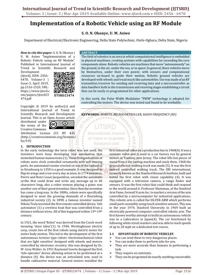
The field of robotics is an area in which computational intelligence is embedded in physical machines, creating systems with capabilities far exceeding the core components alone. Robotic vehicles are machines that move "autonomously on the ground, in the air, under the sea, or in space. In general, these vehicles move by themselves, under their own power, with sensors and computational resources on board to guide their motion. Robotic ground vehicles are developed with wheels and tread much like automobiles. Use was made of an RF transmitter receiver for sending and receiving data and a microcontroller as data handlers both in the transmission and receiving stages establishing a circuit that can be easily re programmed for other applications.In this work, the Pulse Width Modulator "PWM technology is adopted for controlling the motors. The device was tested and found to be workable. S. O. N. Okonye | U. M. Asiwe "Implementation of a Robotic Vehicle using an RF Module" Published in International Journal of Trend in Scientific Research and Development (ijtsrd), ISSN: 2456-6470, Volume-3 | Issue-3 , April 2019, URL: https://www.ijtsrd.com/papers/ijtsrd23474.pdf Paper URL: https://www.ijtsrd.com/engineering/electronics-and-communication-engineering/23474/implementation-of-a-robotic-vehicle-using-an-rf-module/s-o-n-okonye<br>

E N D
International Journal of Trend in Scientific Research and Development (IJTSRD) Volume: 3 | Issue: 3 | Mar-Apr 2019 Available Online: www.ijtsrd.com e-ISSN: 2456 - 6470 Implementation of a Robotic Vehicle using an RF Module S. O. N. Okonye, U. M. Asiwe Department of Electrical/Electronic Engineering, Delta State Polytechnic, Otefe-Oghara, Delta State, Nigeria How to cite this paper: S. O. N. Okonye | U. M. Asiwe "Implementation of a Robotic Vehicle using an RF Module" Published in International Journal of Trend in Scientific Research and Development (ijtsrd), ISSN: 2456- 6470, Volume-3 | Issue-3, April 2019, pp.1516-1520, URL: https://www.ijtsrd.c om/papers/ijtsrd23 474.pdf Copyright © 2019 by author(s) and International Journal of Trend in Scientific Research and Development Journal. This is an Open Access article distributed under the terms of the Creative Commons Attribution License (CC BY 4.0) (http://creativecommons.org/licenses/ by/4.0) 1.INTRODUCTION In the early technology the term robot was not used, the inventors were busy developing real automation that mimicked human mannerisms (1). These first generations of robots were clock controlled ornaments with self-moving parts. An automated rooster erected on top of the cathedral in Strasbourg in 1350 is a good example. It was designed to flap its wings and crow every day at noon. In 1774 inventors, Pierre and Henri Louis Jacquetdroz, unveiled the automatic scribe that could draw and write any message up to 40 characters long; also a robot woman playing a piano was another one of their great invention. Since then the invention has come a long way. In the 1800s, robots were specifically designed to meet the growing demands of a flourishing industrial society (2). In 1898, a famous inventor named Nikola Tesla invented the first remote controlled device, ‘tele automaton’ (1) a crewless boat that was controlled from a distance without wires. All of this happened within 13th-19th century. ABSTRACT The field of robotics is an area in which computational intelligence is embedded in physical machines, creating systems with capabilities far exceeding the core components alone. Robotic vehicles are machines that move “autonomously” on the ground, in the air, under the sea, or in space. In general, these vehicles move by themselves, under their own power, with sensors and computational resources on-board to guide their motion. Robotic ground vehicles are developed with wheels and tread much like automobiles. Use was made of an RF transmitter/receiver for sending and receiving data and a microcontroller as data handlers both in the transmission and receiving stages establishing a circuit that can be easily re-programmed for other applications. In this work, the Pulse Width Modulator “PWM” technology is adopted for controlling the motors. The device was tested and found to be workable. KEYWORDS:ROBOTS, MICROCONTROLLER, RADIO FREQUENCY (RF) IJTSRD23474 first industrial robot on a production line in 1968(4). It was a unimate robot and is used in a car factory run by general motors in Trenton, new Jersey. The robot lifts hot pieces of metal from a die casting machine and stack them. 1968 the general electric walking truck was made (5). It was the first manual controlled walking truck. The SRI international, formerly known as the Stanford Research Institute, built and tested the first robot with vision capability (4). It was equipped with a television camera, a range finder and sensors. It was the first robot that could think and respond to the world around it. Professor Sheinman, of the Stanford Arm Fame, formed Vcarm Inc. to market a version of the arm controlled by a microcomputer for industrial applications. This robotic arm is called the SILVER ARM which performs small parts assembly using touch sensitive sensors. This was in the year 1974. Stanford University in 1969 built an electrically powered computer controlled robotic arm. The first known worthy attempt to build an autonomous vehicle was in a Laboratory in Japan(4). The car functioned by following white street markers and was able to reach speeds of up to 20 mph on a dedicated test course. In 1921, the word ‘Robot’ was derived from the Czech word meaning ‘slave labor’(1). In 1940, Westinghouse electric corp, create two of the first robots using electric motor for entire body motion. This led to the development of the first autonomous tortoise type robots ‘electromechanical robot that are light sensitive’ designed with wheels and motors controlled by electronic circuitry, this was designed by Dr. W. Grey Walter. In 1951 Raymond Goertz designed the first ‘tele-operator’ device allowing action to be performed at a distance (4). His device was an articulated arm, used to handle radioactive material. General motors installed the 1.1 ?You can send them to very dangerous places. ?You can make them to perform jobs for you. ?They are more accurate than humans in performing a task. ?They require no nutrients. ?They can be programed do exactly anything conceivable. ADVANTAGES OF ROBOTIC VEHICLES @ IJTSRD | Unique Paper ID – IJTSRD23474 | Volume – 3 | Issue – 3 | Mar-Apr 2019 Page: 1516
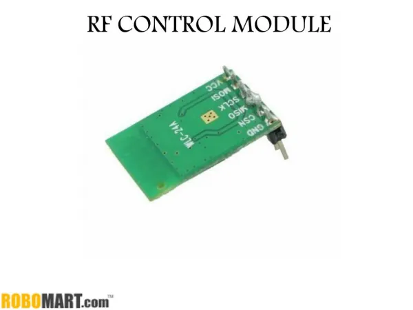
International Journal of Trend in Scientific Research and Development (IJTSRD) @ www.ijtsrd.com eISSN: 2456-6470 1.2 ?They require trained personnel to fix them in the event of anything going wrong. ?They can ruin peoples live by taking their jobs from them. ?They are very expensive to make. ?They can be very hard to program. ?They cannot recharge themselves. 2.SYSTEM DESIGN This system consists of two sections, the transmitter and the receiver section. In transmitter section, keypad is interfaced with the encoder to control the direction of the robot. The encoding data are transferred to the RF receiver where control operation will be performed. In receiver section, the robotic mechanism is interfaced with the controller using a driver circuit. The controller is enhanced with a decoder section for decoding the data from the RF receiver. The decoding data are transferred to the controller for it to analyse the data. The controller then controls the acceleration, direction and sprinkling of the robot based on the data received from the RF receiver. 2.1 BLOCK DIAGRAM OF SYSTEM CONFIGURATION DISADVANTAGES OF ROBOTIC VEHICLES microprocessor, RAM an EPROM, and several ports all on a single chip) takes care of software and hardware interfacing of keyboard. In such systems it is the function of programs stored in the EPROM of microcontroller to scan the keys continuously, identify which one has been activated, and present it to the motherboard. Figure below shows a 4x4 matrix connected to two ports. The rows are connected to an output port and the columns are connected to an input port. If no key has been pressed, reading the input port will yield 1s for all columns since they are all connected to high (Vcc) If all the rows are grounded and a key is pressed, one of the columns will have 0 since the key pressed provides the path to ground. It is the function of the microcontroller to scan the keyboard continuously to detect and identify the key pressed. Fig 3: Key Pad Interface with Microcontroller 2.5 Radio Frequency, any frequency within the electromagnetic spectrum associated with radio wave propagation. When an RF current is supplied to an antenna, an electromagnetic field is created that then is able to propagate through space. Many wireless technologies are based on RF field propagation. Radio Frequency has 10 kHz to 300 GHz frequency range that can be used for wireless communication. Radio Frequency are also used generally to refer to the radio signal generated by the system transmitter, or to energy present from other sources that may be picked up by a wireless receiver. 2.6 TRANSMITTER The TWS-434 is extremely small, and are excellent for application requiring short-range RF remote controls. The transmitter module is only 1/3 the size of a standard postage stamp, and can easily be placed inside a small plastic enclosure. RF MODULE (RADIO FREQUENCY): Fig 1: Block Diagram of Transmitter Section Fig 2: Block Diagram of Receiver Section 2.2 This section deliver constant and regulated output power supply for successful working of the system. A 0-12V/1mA transformer is used for this purpose. The primary of this transformer is connected to the main supply through an on/off switch and fuse for protection against overload and short circuit. The secondary is connected to the diodes to convert 12V AC to 12V DC voltage and filtered by the capacitors, which is further regulated to +5V, by using IC 7805. 2.4 KEYPAD INTERFACING MICROCONTROLLERS: At the lowest level, keyboards are organized in a matrix of rows and columns. The CPU accesses both rows and columns through ports; therefore, with two 8-bit ports, an 8x8 matrix of keys can be connected to a microprocessor. When a key is pressed, a row and column makes contact; otherwise, there is no connection between row and column. In IBMPC keyboards, a single microcontroller (consisting of POWER SUPPLY Fig 4: The TWS-434 Transmitter WITH THE TWS-434: The transmitter output is up to 8mW at 433.92 MHz with a range of approximately 400 foot (open area) outdoors. Indoors, the range is approximately 200 foot, and will go through most walls. 15 The TWS-434 transmitter accepts both linear and digital inputs and can operate from 1.5 to 12 Volts-DC, and makes building a miniature hand- held RF transmitter very easy. The TWS-434 is approximately 1/3 the size of a standard postage stamp. @ IJTSRD | Unique Paper ID – IJTSRD23474 | Volume – 3 | Issue – 3 | Mar-Apr 2019 Page: 1517
International Journal of Trend in Scientific Research and Development (IJTSRD) @ www.ijtsrd.com eISSN: 2456-6470 a 2.7kW series base resistor for each Darlington pair for operation directly with TTL or 5V CMOS devices. The ULN2003 series input resistors selected for operation directly with 5 V TTL or CMOS. These devices will handle numerous interface needs particularly those beyond the capabilities of standard logic buffers. The ULN2003 have series input resistors for operation directly from 6V to 15V CMOS or PMOS logic outputs. The ULN2003 is the standard Darlington arrays. The outputs are capable of sinking 500mA and will withstand at least 50V in the OFF state. Outputs may be paralleled for higher load current capability. The ULx2823A/LW and ULx2824A/ LW will withstand 95V in the off state. These Darlington arrays are furnished in 18-pin dual in line plastic packages or 18-lead small-outline plastic packages (suffix ‘LX’). All devices are pinned with outputs opposite inputs to facilitate ease of circuit board layout. Prefix ‘ULN’ devices are rated for operation over the temperature range of -20oC to +85oC; prefix ‘ULQ’ devices are rated for operation to -40oC. Fig 5: Transmitter Application Circuit 2.7 RWS-434: The receiver also operates at 433.92MHz, and has a sensitivity of 3uV. The RWS-434 operates from 4.5 to5.5 volts-DC, and has both linear and digital outputs. RECEIVER 2.12 ENCODER GENERAL DESCRIPTION The 212 encoders are a series of CMOS LSIs for remote control system applications. They are capable of encoding information which consists of N address bits and 12 N data bits. Each address data input can be set to one of the two logic states. The programmed addresses data are transmitted together with the header bits via an RF or an infrared transmission medium upon receipt of a trigger signal. The capability to select a TE trigger on the HT12E or a DATA trigger on the HT12A further enhances the application flexibility of the 212 series of encoders. The HT12A additionally provides a 38 kHz carrier for infrared systems. Fig 6: Receiver Module 2.8 A 0V to Vcc data output is available on pins. This output is normally used to drive a digital decoder IC or a microprocessor which is performing the data decoding. The receiver’s output will only transition when valid data is present. In instances when no carrier is present the output will remain low. RECEIVER DATA OUTPUT 2.12.1 ADDRESS/ DATA PROGRAMMING (PRESET): The status of each address/data pin can be individual preset to logic “high” or “low”. If a transmission signal is applied, the encoder scans and transmits the status of the 12 bits of address/data serially in the orde A0 to AD11 for the HT12E encoder and A0 to D11 for the HT12a encoder. 2.9 The RWS-434 modules do not incorporate internal decoding. If you want to receive simple control or status signals such as button presses or switch closures, you can use the encoder and decoder IC set described above. Decoders with momentary and latched outputs are available. DECODING DATA During information transmission these bits are transmitted with a proceeding synchronization bit. If the trigger signal is not applied, the chip enters the standby mode and consumes a reduced current of less than 1 f for a supply voltage of 5V. 2.10 TRANSMITTING AND RECEIVING: Full duplex or simultaneous two-way operation is not possible with these modules. If a transmit and receive module are in close proximity and data is sent to a remote receive module while attempting to simultaneously receive data from a remote transmit module, the receiver will be overloaded by its close proximity transmitter. This will happen even if encoders and decoders are used with different address settings for each transmitter and receiver pair. If two way communications is required, only half duplex operation is allowed. Usual applications preset the address pins with individual secuirity codes using DIP switches or PCB wiring, while the data is selected by push buttons or electronic switches. 2.13 DECODER GENERAL DESCRIPTION: The 212 decoders are a series of CMOS LSIs for remote control system applications. They are paired with Holteks 212 series of encoders (refer to the encoder/decoder cross reference table). For proper operation, a pair of encoder/decoder with the same number of addresses and data format should be chosen. The decoders receive serial addresses and data from a programmed 212 series of encoders that are transmitted by a carrier using an RF or an IR transmission medium. They compare the serial input data three times continuously with their local addresses. If no error or output pins, the VT pin also goes high to indicate a valid transmission. The 212 series of bits of data of this series, the HT12D is arranged to provide 8 address bits and 4 data bits, HT12F is used to decode 12 bits of address information. 2.11 DRIVER CIRCUIT: The ULN2003 is a monolithic high voltage and high current Darlington transistor arrays. It consists of seven NPN Darlington pairs that feature high-voltage outputs with common cathode clamp diode for switching inductive loads. The collector-current rating of a single Darlington pair is 500mA. The Darlington pairs may be paralleled for higher current capability. Applications include relay drivers, hammer drivers, lamp drivers, display drivers (LED gas discharge), line drivers, and logic buffers. The ULN2003 has @ IJTSRD | Unique Paper ID – IJTSRD23474 | Volume – 3 | Issue – 3 | Mar-Apr 2019 Page: 1518
International Journal of Trend in Scientific Research and Development (IJTSRD) @ www.ijtsrd.com eISSN: 2456-6470 2.14 In any electric motor, operation is based on simple electromagnetism. A current-carrying conductor generates a magnetic field; when this is then placed in an external magnetic field, it will experience a force proportional to the current in the conductor, and to the strength of the external magnetic field. As you are well aware of from playing with magnets as a kid, opposite (North and South) polarities attract, while like polarities (North and North, South and South) repel. The internal configuration of a DC motor is designed to harness the magnetic interaction between a current-carrying conductor and an external magnetic field to generate rotational motion. DC MOTOR: You’ll notice a few things from this namely, one pole is fully energized at a time (but two others are “partially” energized).As each brush transitions from one accumulator contact to the next, one coil’s field will rapidly collapse, as the next coil’s field will rapidly charge up (this occurs within a few microsecond). In small motors, an alternative design is often used which features a ‘coreless’ armature winding. This design depends upon the coil wire itself for structural integrity. As a result, the armature is hollow, and the permanent magnet can be mounted inside the rotor coil. Coreless dc motors have much lower armature inductance than iron-core motors of comparable size, extending brush and accumulator life. Fig.9: Coreless DC Motors The coreless design also allows manufacturers to build smaller motors; meanwhile, due to the lack of iron in their rotors, coreless motors are somewhat prone to overheating. As a result, this design is generally used just in small, low- power motors 2.15 AT89S52 MICROCONTROLLER: Microprocessors and microcontrollers are widely used in embedded system products(3). Microcontroller is a programmable device. A microcontroller has a CPU in addition to a fixed amount of RAM, ROM I/O ports and a timer embedded all on a single chip. The fixed amount of on- chip ROM or RAM and number of I/O ports in microcontrollers makes them ideal for many applications in which cost and space are critical. The Intel 8051 is Harvard architecture, single chip microcontroller which was developed by Intel in 1980 for use in embedded systems. 8051 is an 8-bit processor, meaning that the CPU can work on only 8 bits of data at a time. Data larger than 8 bits has to be broken into 8-bit pieces to be processed by the CPU, 8051 is available in different memory types such as UV-EPROM, Flash and NV-RAM. The microcontroller used in this work is AT89C51. The present work is implemented on assembly language. In order to program the device, Preload tools has been used to burn the program onto the microcontroller. Fig. 7: DC Electric Motor Every DC motor has six basic parts – axle, rotor (armature), stator, accumulator, field magnet(s), and brushes. In most common DC motors, the external magnetic field is produced by high-strength permanent magnets. The stator is the stationary part of the motor—this includes the motor casing, as well as two or more permanent magnet pole pieces. The rotor (together with the axle and attached accumulator) rotates with respect to the stator. The rotor consists of windings (generally a core), the windings being electrically connected to the accumulator. The above diagram shows a common motor layout – with the rotor inside the stator (field) magnets. The geometry of the brushes, accumulator contacts, and rotor windings are such that when power is applied, the polarities of the energized winding and the stator magnet(s) are misaligned, and the rotor will rotate until it is almost aligned with stator’s field magnets. As the rotor reaches alignment, the brushes move to the next accumulator contacts, and energize the next winding. Given our example of a two-pole motor, the rotation reverses the direction of current through the rotor winding, leading to a “flip” of the rotor’s magnetic field, driving it to continue rotating. In real life, though dc motors will always have more than two poles (three is a very common number). In particular, this avoids “dead spots” in the accumulator. Fig. 8: The DC Motor Showing the Field Poles @ IJTSRD | Unique Paper ID – IJTSRD23474 | Volume – 3 | Issue – 3 | Mar-Apr 2019 Page: 1519
International Journal of Trend in Scientific Research and Development (IJTSRD) @ www.ijtsrd.com eISSN: 2456-6470 investigated and understood. To conclude, the use of battery as a power source for this robotic vehicle is that if the battery is low or damaged, it can be charged or purchased at any electronic shop nearby. 4.2 RECOMMENDATION: Further research could be undertaken in order to increase the abilities of this robot by incorporating such things like obstacle detectors, cameras, robotic arm, microphones, etc. it may also be important to increase the range of operation. One of the primary applications of this robot is that it could be used in the field for surveillance, also for tracking inanimate objects in places where it is not possible to employ surveillance by humans. Cameras can be used to relay live images to a monitor in a station manned by human at the other end. It may also be applicable in rescue operations. For example, in case of fire outbreak the robot could be used to transmit images of the area concerned. If images of any individual requiring to be rescued are picked up, help is immediately sent out. REFERENCES [1]Siegwart, R. and I. R. Nourbakhsh, 2004, “Introduction to autonomous mobile Robots”, Cambridge, MA: MIT Press. Fig.10: The Internal Circuit and the Chassis of the Vehicle 3.1 The tests carried out on the robotic vehicle include: 3.1.1 ELECTRONIC STABILITY CONTROL TEST (ESC) The electronic stability control ESC is active safety system, which improve the dynamic stability of the vehicle. Through selecting brake intervention at individual wheels ESC keep the vehicle on track and prevents it from skidding uncontrollably. 3.1.2 DURABILITY TEST Durability test are important part of a vehicle department. Subsystem or the entire vehicles are stressed under realistic conditions in other to make statement about the durability and reliability. The vehicle’s entire life cycle has to be passed. Endurance test are time consuming and labour intensive, as test the controller must complete several kilometers with the test vehicle to realize the required load profiles. 3.2 RESULT OF TEST In this work, we were able to achieve the control section which includes the wireless communication between the mobile robot and the remote control. The main task of this work was to program the AVR microcontroller using assembly language on the robot to enable us wirelessly control it. This level was successfully tested. 4.1 CONCLUSION: This work has successfully dealt with the control of robotic vehicle using an RF transmitter and receiver. In overall, this work was carried out diligently and with success. From this work, the characteristics of the robotic vehicle was SYSTEM TESTS [2]Thrun, S., W. Burgard and D. Fox, 2005, “Probabilistic robotics. Cambridge”, MA: MIT Press. [3]S. Kamal Viswanath, M. Gowtham, P. Ashok Kumar, K. Rohit Naik, 2011, “Speed control of a dc motor using microcontroller 805”, Gokaraju rangaraju institutes of engineering and technology. [4]Stefan Mitsch, Khalil Ghorbal and Andr’e platzer, 2013, “On probably safe obstacle avoidance for autonomous robotic ground vehicles”, Camegie mellon university, USA. [5]Dr. Robert Finkelstein, 2007, President, Robotic Technology Inc. Military Robotics: Malignant Machines or The Path to Peace. [6]Melonee Wise, 2003, “Digital communication using the PIC16F84A Microcontroller”, Physics Department, University of Illinois. [7]www.allaboutcircuit.com [8]www.robotroom.com/InfraredTransmitter @ IJTSRD | Unique Paper ID – IJTSRD23474 | Volume – 3 | Issue – 3 | Mar-Apr 2019 Page: 1520


![[ Module 5] Requirements for implementation of a CSP](https://cdn1.slideserve.com/1642527/slide1-dt.jpg)