Download
1 / 6
60 likes | 69 Vues
A network redundancy is a key factor to consider for maintaining network reliability. Redundancy is one of special importance in industrial process applications and in safety critical system where network, down time could cause serious problems and production could stop. So, redundancy will be needed to consider to ensure that hosts maintaining network connectivity in the event of failure of one device serving. In this system, campus A and campus B connected point to point link. In the campus A, ether channel and the redundancy protocol is running, and the campus B is running VoIP service. Between the two campuses used Open Shortest Path Fast OSPF routing protocols for the routing among different networks. In the campus A, the Vlan Trunking Protocols VTP is used and Rapid Per Vlan Spanning Tree RPVST is also used to avoid the loop among switches. Ether channel is used to get load balancing and VoIP is also running. The two routers at the edge of core layer are running the Network Address Transition NAT to connect the outside world. This system designed, built DHCP, HSRP, GLBP, Ether channel, OSPF, NAT, STP, VLAN, RPVST , VTP, VoIP and simulated using Cisco Packet Tracer. The results showed that network design is viable and implementation. Khaing Khaing Wai "Network-Level Redundancy for Campus LAN" Published in International Journal of Trend in Scientific Research and Development (ijtsrd), ISSN: 2456-6470, Volume-3 | Issue-5 , August 2019, URL: https://www.ijtsrd.com/papers/ijtsrd26768.pdf Paper URL: https://www.ijtsrd.com/computer-science/computer-network/26768/network-level-redundancy-for-campus-lan/khaing-khaing-wai<br>

E N D
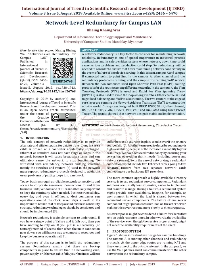
International Journal of Trend in Scientific Research and Development (IJTSRD) Volume 3 Issue 5, August 2019 Available Online: www.ijtsrd.com e-ISSN: 2456 – 6470 Network-Level Redundancy for Campus LAN Khaing Khaing Wai Department of Information Technology Support and Maintenance, University of Computer Studies, Mandalay, Myanmar How to cite this paper: Khaing Khaing Wai "Network-Level Redundancy for Campus LAN" Published in International Journal of Trend in Scientific Research and Development (ijtsrd), ISSN: 2456- 6470, Volume-3 | Issue-5, August 2019, pp.1738-1743, https://doi.org/10.31142/ijtsrd26768 Copyright © 2019 by author(s) and International Journal of Trend in Scientific Research and Development Journal. This is an Open Access article distributed under the terms of the Creative Commons Attribution License (CC (http://creativecommons.org/licenses/by /4.0) 1.INTRODUCTION The sole concept of network redundancy is to provide alternate and efficient paths for data to travel along in case a cable is broken or a connector accidentally unplugged. Ethernet as standard does not have rings or loops in the network because it will cause broadcast storms and can ultimately cause the network to stop functioning. To withstand with redundancy, network building structure mainly the switches and routers [6] used in the network must support redundancy protocols designed to avoid the usual problems of putting loops into a network. ABSTRACT A network redundancy is a key factor to consider for maintaining network reliability. Redundancy is one of special importance in industrial process applications and in safety-critical system where network, down time could cause serious problems and production could stop. So, redundancy will be needed to consider to ensure that hosts maintaining network connectivity in the event of failure of one device serving. In this system, campus A and campus B connected point to point link. In the campus A, ether channel and the redundancy protocol is running, and the campus B is running VoIP service. Between the two campuses used Open Shortest Path Fast (OSPF) routing protocols for the routing among different networks. In the campus A, the Vlan Trunking Protocols (VTP) is used and Rapid Per Vlan Spanning Tree+ (RPVST+) is also used to avoid the loop among switches. Ether channel is used to get load balancing and VoIP is also running. The two routers at the edge of core layer are running the Network Address Transition (NAT) to connect the outside world. This system designed, built DHCP, HSRP, GLBP, Ether channel, OSPF, NAT, STP, VLAN, RPVST+, VTP, VoIP and simulated using Cisco Packet Tracer. The results showed that network design is viable and implementation. KEYWORDS: Network Protocols, Network Redundancy, Cisco Packet Tracer IJTSRD26768 BY 4.0) suffer because a source is in place to take over if the primary source fails [6]. Another term used to describe redundancy is high availability, because of the increased availability to your resources. We have achieved redundancy by ensuring your server has everything that it needs (including power and network source). So in the case of networking, a redundant connection would include two Ethernet cables going to two separate routers from two separate network cards connecting to our backbone ISP providers. The more common approach a highly available directory service is to use redundant server components. Redundant solutions are usually less expensive, easier to implement, and easier to manage. During a failure, a redundant system might provide poor availability. Imagine, for example, an environment in which the load is shared between two redundant server components. The failure of one server component might put an excessive load on the other server, making this sever respond more slowly to client requests. Today, business requires reliable network connectivity and access to corporate resources. Connections to and from business units, vendors and SOHOs are all equally important to keep the continuity when needed. Business runs all day, every day and even in off hours. Most companies run operations around the clock, seven days a week so it’s important to realize that to keep a solid business continuity strategy, redundancy technologies should be considered and should be implemented [3]. A slow response might be considered a failure for clients that rely on quick response times. In other words, the availability of the service, even though the service is operational, might not meet the availability requirements of the client. Network redundancy is a simple concept to understand. If you have a single point of failure and it fails you, then you have nothing to rely on. If you put in a secondary (or tertiary) method of access, then when the main connection goes down, you will have a way to connect to resources and keep the business operational [5]. 2.PROPOSED SYSTEM Figure 1 shows infrastructure design for campus buildings. The campus A is running ether channels and redundancy protocols. At the upper edge routes are running NAT and they can connect to the outside internet. In the campus B, we use the VoIP phones and it can communicate with the other networks in the redundancy campus. The purpose of this system is to build the redundancy system. Redundancy means that there are backup components in place to ensure that if a networking card, power supply, or Ethernet cable fails, your business will not @ IJTSRD | Unique Paper ID – IJTSRD26768 | Volume – 3 | Issue – 5 | July - August 2019 Page 1738
International Journal of Trend in Scientific Research and Development (IJTSRD) @ www.ijtsrd.com eISSN: 2456-6470 SW02(config)#interface range f0/1-2 SW02(config-if)#shutdown SW02(config-if)#channel-group 2 mode desirable SW02(config-if)#no shut SW02(config-if)#interface port-channel 2 SW02(config-if)#switchport mode trunk SW03(config)#interface range f0/1-2 SW03(config-if)#shutdown SW03(config-if)#channel-group 2 mode desirable SW03(config-if)#no shut SW03(config-if)#interface port-channel 2 SW03(config-if)#switchport mode trunk SW03(config)#interface range f0/5-6 SW03(config-if)#shutdown SW03(config-if)#channel-group 3 mode desirable SW03(config-if)#no shut SW03(config-if)#interface port-channel 3 SW03(config-if)#switchport mode trunk 3.3 OSPF Configuration on Routers R01(config)#router ospf 10 R01(config-router)#router-id 1.1.1.1 R01(config-router)#log-adjacency-changes R01(config-router)#network 192.168.3.0 0.0.0.255 area 0 R01(config-router)#network 192.168.2.0 0.0.0.255 area 0 R01(config-router)#network 192.168.10.0 0.0.0.255 area0 R01(config-router)#network 192.168.11.0 0.0.0.255 area 0 R01(config-router)#network 192.168.12.0 0.0.0.255 area 0 R01(config-router)#network 203.81.64.192 0.0.0.7 area 0 R02(config)#router ospf 10 R02(config-router)#router-id 2.2.2.2 R02(config-router)#log-adjacency-changes R02(config-router)#network 192.168.2.0 0.0.0.255 area 0 R02(config-router)#network 192.168.4.0 0.0.0.255 area 0 R02(config-router)#network 192.168.10.0 0.0.0.255 area 0 R02(config-router)#network 192.168.11.0 0.0.0.255 area 0 R02(config-router)#network 192.168.12.0 0.0.0.255 area 0 R03(config)#router ospf 10 R03(config-router)#router-id 3.3.3.3 R03(config-router)#log-adjacency-changes R03(config-router)#network 192.168.3.0 0.0.0.255 area 0 R03(config-router)#network 192.168.4.0 0.0.0.255 area 0 R03(config-router)#network 192.168.10.0 0.0.0.255 area 0 R03(config-router)#network 192.168.11.0 0.0.0.255 area 0 R03(config-router)#network 192.168.12.0 0.0.0.255 area 0 3.4 VoIP Services Configuration R04(config)#telephony-service R04(config-telephony)#max-ephones 5 R04(config-telephony)#max-dn5 R04(config-telephony)#ip source-address 192.168.1.1 port 2000 R04(config-telephony)#auto assign 1 to 9 R04(config)#ephone-dn 1 R04(config-ephone-dn)#number 100 R04(config)#ephone-dn 2 R04(config-ephone-dn)#number 200 3.5 NAT Configuration R01(config)# ip nat inside source list 1 interface Serial0/1/0 overload R01(config)# ip route 0.0.0.0 0.0.0.0 Serial0/1/0 Figure1. Network Infrastructure Design 3.IMPLEMENTION In this design, four Cisco 1900 series routers, four Cisco 2960 series switches, personal computers (PCs), two IP phones are used as main networking components. Gateway Load Balancing Protocol (GLBP) is used for redundancy. Ether channel is a form of link aggregation used in switched networks. It also provides redundancy because the overall link is viewed as on logical connection by Spanning Tree Protocol (STP). If one physical link within channel goes down, this does not cause a change in the topology and does not require STP recalculation. RPVST+s support 802.1q and works as IEEE 802.1w. Vlan VTPs and RPVST+ are used to avoid the loop among switches. In this system OSPF protocol is used to route and to get connections between the different networks. NAT is also used the system to connect with outside network. 3.1 Redundancy Configuration R02(config)#interface g0/1 R02(config-if)#glbp 1 ip 192.168.1.254 R02(config-if)#glbp 1 preempt R02(config-if)#glbp 1 priority 150 R02(config-if)#glbp 1 load-balancing round-robin R03(config)#interface g0/0 R03(config-if)#glbp 1 ip 192.168.1.254 R02(config-if)#glbp 1 load-balancing round-robin 3.2 EtherChannel Configuration on Switches SW01(config)#interface range f0/3-4 SW01(config-if)#shutdown SW01(config-if)#channel-group 1 mode desirable SW01(config-if)#no shut SW01(config-if)#interface port-channel 1 SW01(config-if)#switchport mode trunk SW01(config)#interface range f0/5-6 SW01(config-if)#shutdown SW01(config-if)#channel-group 3 mode desirable SW01(config-if)#no shut SW01(config-if)#interface port-channel 3 SW01(config-if)#switchport mode trunk SW02(config)#interface range f0/3-4 SW02(config-if)#shutdown SW02(config-if)#channel-group 1 mode desirable SW02(config-if)#no shut SW02(config-if)#interface port-channel 1 SW02(config-if)#switchport mode trunk @ IJTSRD | Unique Paper ID – IJTSRD26768 | Volume – 3 | Issue – 5 | July - August 2019 Page 1739
International Journal of Trend in Scientific Research and Development (IJTSRD) @ www.ijtsrd.com eISSN: 2456-6470 R01(config)# access-list 1 permit 192.168.0.0 0.0.255.255 R01(config)# interface GigabitEthernet0/1 R01(config-if)# ip address 192.168.3.1 255.255.255.0 R01(config-if)# ip nat inside R01(config)# interface GigabitEthernet0/0 R01(config-if)# ip address 192.168.2.1 255.255.255.0 R01(config-if)# ip nat inside R01(config)# interface Serial0/1/0 R01(config-if)# ip address 203.81.64.193 255.255.255.248 R01(config-if)# ip nat outside R04(config)# interface GigabitEthernet0/0 R04(config-if)# ip address 192.168.1.1 255.255.255.0 R04(config-if)# ip nat inside R04(config)# interface Serial0/1/0 R04(config-if)# ip address 203.81.64.194 255.255.255.248 3.7 Testing Result The following figures show the result for the system. R04(config-if)# ip nat outside R04(config)# ip nat inside source list 1 interface Serial0/1/0 overload R04(config)# ip route 0.0.0.0 0.0.0.0 Serial0/1/0 R04(config)# access-list 1 permit 192.168.1.0 0.0.0.255 3.6 RPVST+ Configuration on Switches SW01(config)# spanning-tree mode rapid-pvst SW01(config)# spanning-tree vlan 10 root primary SW01(config)# spanning-tree vlan 11-13 root secondary SW02(config)# spanning-tree mode rapid-pvst SW02(config)# spanning-tree vlan 11 root primary SW02(config)# spanning-tree vlan 10,12,13 root secondary SW03(config)# spanning-tree mode rapid-pvst SW03(config)# spanning-tree vlan 12 root primary SW03(config)# spanning-tree vlan 10,11,13 root secondary Figure2. Ether channel Testing in Switch SW01 Figure3. Ether channel Testing in Switch SW02 @ IJTSRD | Unique Paper ID – IJTSRD26768 | Volume – 3 | Issue – 5 | July - August 2019 Page 1740
International Journal of Trend in Scientific Research and Development (IJTSRD) @ www.ijtsrd.com eISSN: 2456-6470 Figure4. Ether channel Testing in Switch SW03 Figure5. OSPF Testing on Cisco Router 01 @ IJTSRD | Unique Paper ID – IJTSRD26768 | Volume – 3 | Issue – 5 | July - August 2019 Page 1741
International Journal of Trend in Scientific Research and Development (IJTSRD) @ www.ijtsrd.com eISSN: 2456-6470 Figure6. Testing Result for VLAN Figure7. Redundancy Protocol GLBP Testing @ IJTSRD | Unique Paper ID – IJTSRD26768 | Volume – 3 | Issue – 5 | July - August 2019 Page 1742
International Journal of Trend in Scientific Research and Development (IJTSRD) @ www.ijtsrd.com eISSN: 2456-6470 [5]http://techgenix.com/importance-network- redundancy/ 4.CONCLUSION Redundant devices, such as multilayer switches or routers, provide the capability for a client to use an alternate default gateway when primary default gateway fails. First Host Redundancy protocols, such as HSRP, VRRP, and GLBP provide alternate default gateways for hosts in the redundant router or multilayer switched environment. In this system, a network redundancy is a key factor to consider for maintaining network reliability. So, Layer 3 redundancy will be needed to consider to ensure that hosts maintain connectivity in the event of link failure of one device serving as a default gateway for a VLAN or set of VLANs. 5.REFERENCES [1]James F. Kurose & Keith W. Ross, “Computer Network A Top Down Approach”, 6th ed., 2013. [6]Todd Lammle, "CCNA", sixth Edition [7]Nathaniel S. Tarkaa, Paul I. Iannah, IsaacT. Iber "design and simulation of local area network using cisco pocket tracer", the International Journal of Engineering and Science (IJES), volume 6, issue 10, page 63-77, 2017. [8]Current, John R., Charles S. ReVelle, and Jared L. Cohon. "The hierarchical network design problem." European Journal of Operational Research 27.1 (1986): 57-66. [9]Paulami Pathak, Sayanti Majumder, Chandra mondal, prof. Manikandan K "College Network Scenario Implementation by Using Cisco Packet Tracer", International Journal of Advance Research in Computer and Communication Engineering (IJARCCE), volume 7, issue 1, January 2017. [2]“Network Basics Companion Guide, Cisco Networking Academy, Cisco Press, 2014. [10]Garima Jain, Nasreen Noorani, Nisha Kiran, Sourabh Sharma, Designing & simulation of topology network using Packet Tracer, International Research Journal of Engineering and Technology (IRJET), 2(2), 2015. [3]Cisco Systems Inc. http://www.cisco.com [4]Khaing Khaing Wai et. al. / International Journal of New Technologies in Science and Engineering, Vol. 6, Issue. 5, 2019. @ IJTSRD | Unique Paper ID – IJTSRD26768 | Volume – 3 | Issue – 5 | July - August 2019 Page 1743