Download
1 / 3
40 likes | 57 Vues
In quantum dot cellular automata emerge the electronic circuits. This technology takes more attention because of current silicon transistor technology faces many problems. The main advantages of QCA is fast speed and low power consumption. A quantum dot cell can be used to make gates AND, OR and NAND wires and memories also. The QCA has main benefits is faster speed reduced size digital circuits and minimum power consumption. In this paper QCA circuit design basic logic gate with the help of MV, Invertors and QCA wire. Jayshree Chouksey | Er. Deepak Pancholi "Review Paper on Quantum Dot Cellular Automata Using Nanoelectronics" Published in International Journal of Trend in Scientific Research and Development (ijtsrd), ISSN: 2456-6470, Volume-2 | Issue-5 , August 2018, URL: https://www.ijtsrd.com/papers/ijtsrd18214.pdf Paper URL: http://www.ijtsrd.com/engineering/electronics-and-communication-engineering/18214/review-paper-on-quantum-dot-cellular-automata-using-nanoelectronics/jayshree-chouksey<br>

E N D
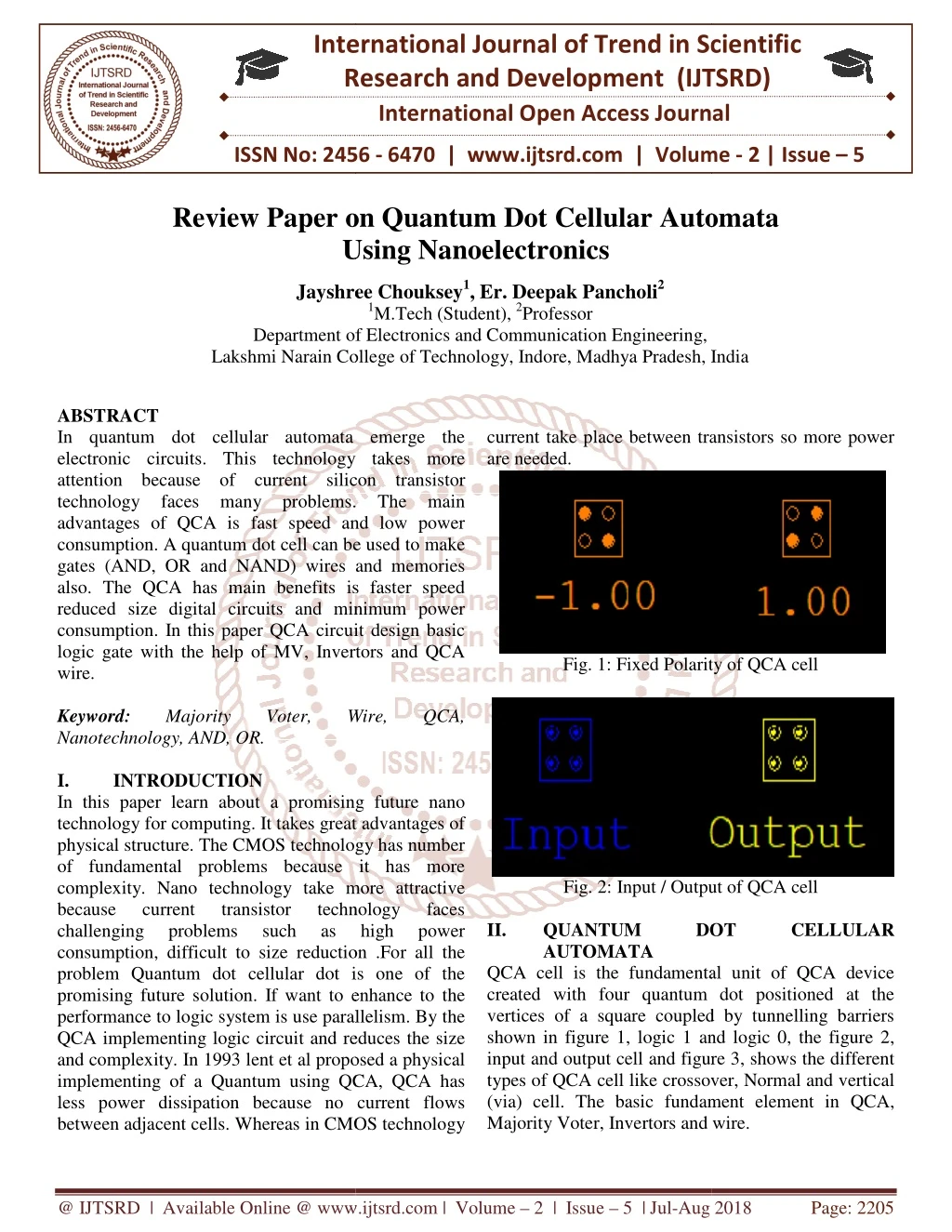
International Research Research and Development (IJTSRD) International Open Access Journal Review Paper on Quantum Dot Cellular Automata Using Nanoelectronics International Journal of Trend in Scientific Scientific (IJTSRD) International Open Access Journal ISSN No: 2456 ISSN No: 2456 - 6470 | www.ijtsrd.com | Volume 6470 | www.ijtsrd.com | Volume - 2 | Issue – 5 Review Paper o tum Dot Cellular Automata Using Jayshree Jayshree Chouksey1, Er. Deepak Pancholi2 1M.Tech (Student), 2Professor Department of Electronics and Communication Engineering, Lakshmi Narain College of Technology, Indore, Madhya Pradesh, India Department of Electronics and Communication Engineering Lakshmi Narain Coll India ABSTRACT In quantum dot cellular automata emerge the electronic circuits. This technology takes more attention because of current silicon transistor technology faces many problems. The main advantages of QCA is fast speed and low power consumption. A quantum dot cell can be used to make gates (AND, OR and NAND) wires and memories also. The QCA has main benefits is faster speed reduced size digital circuits and minimum power consumption. In this paper QCA circuit design basic logic gate with the help of MV, Invertors and QCA wire. Keyword: Majority Nanotechnology, AND, OR. I. INTRODUCTION In this paper learn about a promising future nano technology for computing. It takes great advantages of physical structure. The CMOS technology has number of fundamental problems because it has more complexity. Nano technology take more attractive because current transistor challenging problems such consumption, difficult to size reduction .For all the problem Quantum dot cellular dot is one of the promising future solution. If want to enhance to the performance to logic system is use parallelism. By the QCA implementing logic circuit and reduces the size and complexity. In 1993 lent et al proposed a physical implementing of a Quantum using QCA, QCA has less power dissipation because no current flows between adjacent cells. Whereas in CMOS technology current take place between transistors so more power are needed. automata emerge the current take place between transistors so more power electronic circuits. This technology takes more attention because of current silicon transistor technology faces many problems. The main advantages of QCA is fast speed and low power consumption. A quantum dot cell can be used to make ates (AND, OR and NAND) wires and memories also. The QCA has main benefits is faster speed reduced size digital circuits and minimum power consumption. In this paper QCA circuit design basic logic gate with the help of MV, Invertors and QCA Fig. 1: Fixed Polarity of QCA cell Fig. 1: Fixed Polarity of QCA cell Majority Voter, Voter, Wire, Wire, QCA, QCA, In this paper learn about a promising future nano technology for computing. It takes great advantages of physical structure. The CMOS technology has number of fundamental problems because it has more complexity. Nano technology take more attractive current transistor challenging problems such consumption, difficult to size reduction .For all the problem Quantum dot cellular dot is one of the promising future solution. If want to enhance to the em is use parallelism. By the QCA implementing logic circuit and reduces the size and complexity. In 1993 lent et al proposed a physical implementing of a Quantum using QCA, QCA has less power dissipation because no current flows ereas in CMOS technology Fig. 2: Input / Output of QCA cell Fig. 2: Input / Output of QCA cell II. technology as high as high technology faces power power faces QUANTUM AUTOMATA QCA cell is the fundamental unit of QCA device created with four quantum dot positioned at the vertices of a square coupled by tunnelling barriers shown in figure 1, logic 1 and logic 0, the figure 2, input and output cell and figure 3, shows the different types of QCA cell like crossover, Normal and v (via) cell. The basic fundament element in QCA, Majority Voter, Invertors and wire. Majority Voter, Invertors and wire. QUANTUM DOT DOT CELLULAR CELLULAR QCA cell is the fundamental unit of QCA device created with four quantum dot positioned at the vertices of a square coupled by tunnelling barriers shown in figure 1, logic 1 and logic 0, the figure 2, input and output cell and figure 3, shows the different types of QCA cell like crossover, Normal and vertical (via) cell. The basic fundament element in QCA, @ IJTSRD | Available Online @ www.ijtsrd.com @ IJTSRD | Available Online @ www.ijtsrd.com | Volume – 2 | Issue – 5 | Jul-Aug 2018 Aug 2018 Page: 2205
International Journal of Trend in Scientific Research and Development (IJTSRD) ISSN: 2456-6470 B.QCA Majority voter In the majority gate, the cells on top, at the left and at the bottom work as input connection cells. As the Coulomb forces of the electrons of all input cells sum up, the middle cell adjusts to the majority of adjustments of the input connection cells. Finally the output cell adjusts to the middle cell and the resulting state of the majority voter equation shown in 1. Y=A.B+B.C+C.A (1) Fig. 3: Different types of cell arrangements A.QCA WIRE The simplest practical cell arrangement is given by placing quantum dot cells in series to the side of each other. The bounding boxesis the figure do not represent physical implementing but we shown as mean to identify individual cells. The rest of cell would immediately synchronize polarization due to columbic introduced between them configuration of such wire can form a complete set of logic gates for computation. There is basically two types of wire A.a simple binary wire B.An invertor’s chain which is constituted by placing 45 degree cell side by side. In figure 4, shows the different QCA cell wire. to the new Fig. 5: Majority voter Fig. 6: Waveform of Majority Voter C.QCA Invertors Gate It is also possible to build a QCA NOT gate. The implementation in QCA takes advantage of geometry of cell adjustments. One QCA wire is forked to two wires, the switch of the cell adjustment takes place by putting the output cell next to the forked wires so that only corners are touching. This makes a 1 at the input a 0 at the output and vice versa. Fig. 4: QCA Design for Wire using 12 Quantum Cells as consider 900 (Normal cell) cell @ IJTSRD | Available Online @ www.ijtsrd.com | Volume – 2 | Issue – 5 | Jul-Aug 2018 Page: 2206
International Journal of Trend in Scientific Research and Development (IJTSRD) ISSN: 2456-6470 Fig. 7: QCA Invertors Gate Fig. 10: QCA Clock-Zone IV. QCA represents one of the novel technologies that is emerging as possible replacement for CMOS. The proposed design are a solution for the implementing of QCA based circuit using minimum number of QCA cells lesser clock delays will be very compact . This paper present fundamental design of QCA cell based Majority voter, Invertors and Wire. REFERENCES 1.C. H. Bennett, “Logical computation,” IBM Journal of Research and Development, vol. 17, no. 6,pp. 525–532, 1973. 2.X. Ma, J. Huang, C. Metra, and F. Lombardi, “Reversible gates and dimensional arrays of molecular QCA,” Journal of Electronic Testing: Theory and Applications, vol. 24, no.1–3, pp.297–311,2008. 3.C. S. Lent, P. D. Tougaw, W. Porod, and G. H. Bernstein, “Quantumcellularautomata,”Nanotechnology,vol. 4,no.1,pp. 49–57,1993. 4.C. S. Lent and P .D. Tougaw “Line so fainter acting quantum-dot cells: a binary wire,” Journal of Applied Physics, vol. 74, no. 10, pp.6227– 6233, 1993. 5.M. Askari, M. Taghizadeh, and K. Fardad, “Digital design using quantum-dot cellular automata (an a nontechnology method),”in Proceedings of the International Conference on Computer and Communication (ICCCE ’08), pp. 952–955, IEEE, Kuala Lumpur, Malaysia, May2008. CONCLUSION Fig. 8: Waveform of QCA Invertors III. Clock zones are a tricky challenge of QCA. They avoid random adjustments of QCA cells and “guide” the information flow, in particular the data propagation, through QCA circuits. In contrast to transistor-based circuits, one clock cycle consists of four clock signals, which are delayed by ¼ of the whole clock cycle among each other, as depicted in figure 9. Single clock has four clock zones and each clock zone has four phases. Basically it works on 4 phase Switch ,Hold , release & relax. QCA CLOCK reversibility of testability of one Engineering Fig. 9: QCA Clock cycle @ IJTSRD | Available Online @ www.ijtsrd.com | Volume – 2 | Issue – 5 | Jul-Aug 2018 Page: 2207