Download

1 / 4
40 likes | 43 Vues
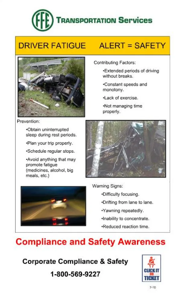
Accidents occurred at night time are mainly due to carelessness of human being such as sleepiness. To avoid that we design and develop a control system based on intelligent electronically controlled automotive braking system. It consists of IR transmitter and receiver circuit, control unit, pneumatic breaking system. The IR sensor is used to monitor the eye blink movement. If the eye blink movement varies beyond the normal condition set 3 sec the IR sends the control signal to the breaking system through electronic control unit ECU . Thus the pneumatic breaking system is used to break the system and alerts the driver to not sleep. From this accidents can prevent before it occurs. Chandra Mohan M | Arivazhagan. A "Vehicle Safety Speed Controller under Driver Fatigue Using Eye Blink Sensor" Published in International Journal of Trend in Scientific Research and Development (ijtsrd), ISSN: 2456-6470, Volume-2 | Issue-1 , December 2017, URL: https://www.ijtsrd.com/papers/ijtsrd7130.pdf Paper URL: http://www.ijtsrd.com/engineering/computer-engineering/7130/vehicle-safety-speed-controller-under--driver-fatigue-using-eye-blink-sensor/chandra-mohan-m<br>

E N D
International Research Research and Development (IJTSRD) International Open Access Journal International Open Access Journal International Journal of Trend in Scientific Scientific (IJTSRD) ISSN No: 2456 - 6470 | www.ijtsrd.com | Volume ehicle Safety Speed Controller under ISSN No: 2456 | www.ijtsrd.com | Volume - 2 | Issue – 1 Vehicle Safety Speed Controller u Driver Fatigue Using Eye Blink Sensor Driver Fatigue Using Eye Blink Sensor Chandra Mohan M Assistant Professor, Department of Mechatronics Engineering, M.A.M School of Engineering, Trichy, India Engineering, Trichy, India Arivazhagan. A Arivazhagan. A Assistant Professor, Department of Mechatronics Engineering, M.A.M School of Assistant Professor, Department of Computer Science and Engineering, M.A.M School of Assistant Professor, Department of Computer Science and Engineering, M.A.M School of Engineering, Trichy, India gineering, Trichy, India ABSTRACT Accidents occurred at night time are mainly due to carelessness of human being such as sleepiness. To avoid that we design and develop a control system based on intelligent automotive braking system. It consists of IR transmitter and receiver circuit, control unit, pneumatic breaking system. The IR sensor is used to monitor the eye blink movement. If the eye blink movement varies beyond the normal condition set (3 sec); the IR sends the control signal to the breaking system through control unit (ECU). Thus the pneumatic breaking system is used to break the system and alerts the driver to not sleep. From this accidents can prevent before it occurs. Keywords: Electronic Control Unit, Interface Controller etc I. INTRODUCTION Accidents occurred at night time are mainly due to carelessness of human being such as sleepiness. To avoid that we design and develop a control system based on intelligent active the relay unit and automatic breaking is applied. active the relay unit and automatic breaking is applied. So driver should be alerted. II. METHODOLOGY electronically electronically consists of IR transmitter controlled controlled re we use PIC microcontroller to burn the program and to control the pneumatic breaking system. It acts as a intermediator between human and vehicle. PIC is a family of modified microcontrollers made by Microchip Technology, om the PIC1650 originally developed General Instrument's Microelectronics Division. The name PIC initially referred to "Peripheral Interface " only. PICs are popular with both industrial developers and hobbyists alike due to eir low cost, wide availability, large user base, extensive collection of application notes, availability of low cost or free development tools, and serial programming with flash memory) Here we use PIC microcontroller to burn the program and to control the pneumatic breaking system. It acts as a intermediator between human and vehicle. family of modified microcontrollers made by Microchip Technology, derived from the PIC1650 by General Instrument's Microelectronics Division. The name PIC initially referred to " Controller" now it is "PIC" only. PICs are popular with both industrial developers and hobbyists alike due to their low cost, wide availability, large user base, extensive collection of application notes, availability of low cost or free development tools, and serial programming (and re-programming with flash memory) capability. and receiver circuit, control unit, pneumatic breaking system. The IR sensor is used to monitor the eye blink movement. If the eye blink movement varies beyond the normal condition set (3 sec); the IR sends the control signal to the breaking system through electronic control unit (ECU). Thus the pneumatic breaking system is used to break the system and alerts the driver to not sleep. From this accidents can prevent before it Harvard Harvard architecture architecture Electronic Control Unit,Peripheral In this project microcontroller is used to sense the eye blink status and control the other units. This project consists of microcontroller, relay driver circuit, infra red sensor unit. When the eye blinking normal level is set to the microcontroller by the programming microcontroller and monitoring the eye blinking pulses with the set pulses. If the eye blinking is normal in microcontroller then it maintains the system in normal condition. When the eye blinking is below the set level that is when driver goes to sleep, this signal are collected from infra-red sensor unit, after receiving this low level pulses from microcontroller it immediately low level pulses from microcontroller it immediately In this project microcontroller is used to sense the eye blink status and control the other units. This project consists of microcontroller, relay driver circuit, infra- red sensor unit. When the eye blinking normal level is troller by the programming microcontroller and monitoring the eye blinking pulses with the set pulses. If the eye blinking is normal in microcontroller then it maintains the system in normal condition. When the eye blinking is below the set level hen driver goes to sleep, this signal are red sensor unit, after receiving this PNEUMATICS: The word ‘pneuma’ comes f breather wind. The word pneumatics is the study of air movement and its phenomena is derived from the word pneuma. Today pneumatics is mainly understood to means the application of air as a working medium in industry especially the driv machines and equipment. Pneumatics has for some considerable time between used for carrying out the simplest mechanical tasks in more recent times has played a more important role in the development of played a more important role in the development of The word ‘pneuma’ comes from Greek and means breather wind. The word pneumatics is the study of air movement and its phenomena is derived from the word pneuma. Today pneumatics is mainly understood to means the application of air as a working medium in industry especially the driving and controlling of Pneumatics has for some considerable time between used for carrying out the simplest mechanical tasks in more recent times has @ IJTSRD | Available Online @ www.ijtsrd.com @ IJTSRD | Available Online @ www.ijtsrd.com | Volume – 2 | Issue – 1 | Nov-Dec 2017 Dec 2017 Page: 1373
International Journal of Trend in Scientific Research and Development (IJTSRD) ISSN: 2456 International Journal of Trend in Scientific Research and Development (IJTSRD) ISSN: 2456 International Journal of Trend in Scientific Research and Development (IJTSRD) ISSN: 2456-6470 pneumatic technology for automation. systems operate on a supply of compressed air which must be made available in sufficient quantity and at a pressure to suit the capacity of the system. A compressor is a machine that takes in air, gas at a certain pressure and delivered the air at a high pressure. Compressor capacity is the actual quantity of air compressed and delivered and the volume expressed is that of the air at intake conditions namely at atmosphere pressure and normal ambient temperature. The compressibility of the air was first investigated by Robert Boyle in 1962 and that found that the product of pressure and volume of a particular quantity of gas. IV. BLOCK DIAGRAM tion. Pneumatic III. systems operate on a supply of compressed air which must be made available in sufficient quantity and at a pressure to suit the capacity of the system. A compressor is a machine that takes in air, gas at a COMPONENTS USED COMPONENTS USED PNEUMATIC COMPONENTS: PNEUMATIC COMPONENTS: i. Solenoid valve ii. Flow control valve iii. Connectors iv. Double acting Pneumatic cylinder ELECTRONIC COMPONENT: i. IR SENSOR UNIT ii. Relay circuits air at a high pressure. Compressor capacity is the actual quantity of air compressed and delivered and the volume expressed is that of the air at intake conditions namely at atmosphere pressure and normal ambient temperature. Double acting Pneumatic cylinder ELECTRONIC COMPONENT: r was first investigated by Robert Boyle in 1962 and that found that the product of pressure and volume of a particular quantity of gas. WORKING OPERATION V. The IR TRANSMITTER circuit is to transmit the Infra rays reflected. This reflected Infra-Red rays are received by the receiver circuit is called “IR RECEIVER”. The IR receiver circuit receives the reflected IR rays and giving the control signal to the control circuit. The control circuit is used to activate the solenoid valve. The chapter. If the solenoid valve is activated, the compressed air passes to the Double Acting Pneumatic Cylinder. The compressed air activates the pneumatic cylinder and moves the piston the breaking arrangement activated. The breaking arrangement is used to break the wheel gradually or suddenly due to the piston movement. The breaking speed is varied by adjusting the valve is called “FLOW CONTROL VALVE”. In our project, we have to apply this breaking arrangement in one wheel as a model. The compressed air drawn from the compressor in our project. control valve. The flow control valve is connected to the solenoid valve as mentioned in the block diagram. s connected to the solenoid valve as mentioned in the block diagram. s connected to the solenoid valve as mentioned in the block diagram. Red rays. If any obstacle is there in a path, the Infra-Red Red rays are received by the receiver circuit is called “IR RECEIVER”. The IR receiver circuit receives the reflected IR rays and giving the control signal to the control circuit. The control circuit operating principle of solenoid valve is already explained in the above chapter. If the solenoid valve is activated, the compressed air passes to the Double Acting Pneumatic Cylinder. The IR TRANSMITTER circuit is to transmit the Infra-Red rays. If any obstacle is there in a path, the Infra Red rays are received by the receiver circuit is called “IR RECEIVER”. The IR receiver circuit receives the reflected IR rays and giving the control signal to the control circuit. The control circuit is used to activate the solenoid valve. The operating principle of solenoid valve is already explained in the above chapter. If the solenoid valve is activated, the compressed air passes to the Double Acting Pneumatic Cylinder. The compressed air activates the pneumatic cylinder and moves the piston rod. If the piston moves forward, then the breaking arrangement activated. The breaking arrangement is used to break the wheel gradually or suddenly due to the piston movement. The breaking speed is varied by adjusting the valve is called “FLOW CONTROL LVE”. In our project, we have to apply this breaking arrangement in one wheel as a model. The compressed air drawn from the compressor in our project. The compressed air flow through the Polyurethane tube to the flow The compressed air flow through the Polyurethane tube to the flow rod. If the piston moves forward, then the breaking arrangement activated. The breaking arrangement is used to break the wheel gradually or suddenly due to the piston movement. The breaking speed is varied by adjusting the valve is called “FLOW CONTROL LVE”. In our project, we have to apply this breaking arrangement in one wheel as a model. The compressed air @ IJTSRD | Available Online @ www.ijtsrd.com @ IJTSRD | Available Online @ www.ijtsrd.com | Volume – 2 | Issue – 1 | Nov-Dec 2017 Dec 2017 Page: 1374
International Journal of Trend in Scientific Research and Development (IJTSRD) ISSN: 2456-6470 VI. DESIGN OF FABRICATED MODEL VII. APPLICATION XII. SNAPSHOTS i. ii. For automobile application Industrial application VIII.ADVANTAGES i. ii. iii. iv. v. vi. vii. Brake cost will be less. Free from wear adjustment. Less power consumption Less skill technicians is sufficient to operate. It gives simplified very operation. Installation is simplified very much. To avoid other burnable interactions viz.… (Diaphragm) is not used. Less time and more profit Accident should be avoided easily monitor the driver’s actions. viii. ix. XI. DISADVANTAGE i. ii. Difficult to implement Sudden break may lead to hit the vehicle by other vehicle who rides back of him. @ IJTSRD | Available Online @ www.ijtsrd.com | Volume – 2 | Issue – 1 | Nov-Dec 2017 Page: 1375
International Journal of Trend in Scientific Research and Development (IJTSRD) ISSN: 2456-6470 REFERENCES 1.G.B.S. Khanna Publishers, Delhi, 1991, pp 671. Narang, “Automobile Engineering”, 2.William H. Crowse, “Automobile Engineering”. 3.Donald. L. Anglin, “Automobile Engineering”. 4.Pneumatic Control System----Stroll &Bernaud, Tata McGraw Hill Publications, 1999. 5.Pneumatic System-Majumdhar, New Age India International (P) Ltd Publishers, 1997. 6.Introduction Applications – by T.R.Padmanabhan (Author) to Microcontrollers 9 and their 2012 Apr @ IJTSRD | Available Online @ www.ijtsrd.com | Volume – 2 | Issue – 1 | Nov-Dec 2017 Page: 1376