Download
1 / 4
40 likes | 45 Vues
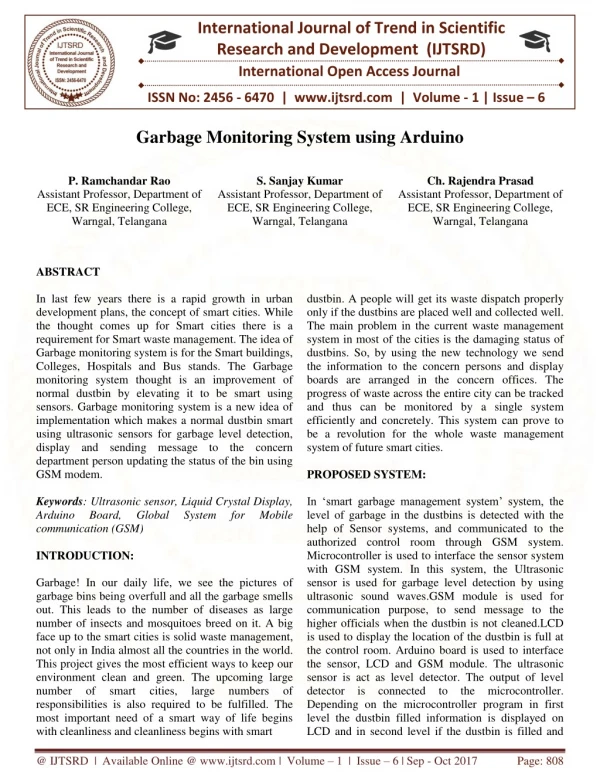
A glace view of our idea is designing a new innovative idea which can monitor the flow of power supply to the existing plug sockets. As in India demand for electricity is increasing day by day, there is a need to implement an idea in order to meet this problem. So not only synthesizing an method to generate the electricity but also a method to save the electricity. Even though there are smart house systems basing on home automation, they only disconnect the electrical or electronic devices form the supply but the power supply to the socket in which the appliance is plugged in can't be stopped. The myth about overcharging your phone is a common one. The amount of charge going into your device shouldnt be an issue as most are smart enough to stop taking a charge once full, just topping up as needed to stay at 100 per cent. The problems occur when the battery overheats, which can cause damage. So.in our paper we are proposing and implementing the automated timer socket using arduino for real time applications. G. Chakra Mahesh Babu | I. Mahesh Veera Bhadrarao | M. Venkata Balaji | Ch. Sai Praveen "Automated Timer Socket using Arduino" Published in International Journal of Trend in Scientific Research and Development (ijtsrd), ISSN: 2456-6470, Volume-3 | Issue-3 , April 2019, URL: https://www.ijtsrd.com/papers/ijtsrd23157.pdf Paper URL: https://www.ijtsrd.com/engineering/electrical-engineering/23157/automated-timer-socket-using-arduino/g-chakra-mahesh-babu<br>

E N D
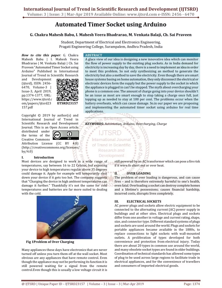
International Journal of Trend in Scientific Research and Development (IJTSRD) Volume: 3 | Issue: 3 | Mar-Apr 2019 Available Online: www.ijtsrd.com e-ISSN: 2456 - 6470 Automated Timer Socket using Arduino G. Chakra Mahesh Babu, I. Mahesh Veera Bhadrarao, M. Venkata Balaji, Ch. Sai Praveen Student, Department of Electrical and Electronics Engineering, Pragati Engineering College, Surampalem, Andhra Pradesh, India How to cite this paper: G. Chakra Mahesh Babu | I. Mahesh Veera Bhadrarao | M. Venkata Balaji | Ch. Sai Praveen "Automated Timer Socket using Arduino" Published in International Journal of Trend in Scientific Research and Development (ijtsrd), ISSN: 2456- 6470, Volume-3 | Issue-3, April 2019, pp.1374-1377, URL: https://www.ijtsrd.c om/papers/ijtsrd23 157.pdf Copyright © 2019 by author(s) and International Journal of Trend in Scientific Research and Development Journal. This is an Open Access article distributed under the terms of the Creative Commons Attribution License (CC BY 4.0) (http://creativecommons.org/licenses/ by/4.0) I. Introduction Most devices are designed to work in a wide range of temperatures, say between 16 to 22 Celsius, but exposing your device to high temperatures regular above 35 degrees could damage it. Apple for example will temporarily shut down your device if it gets too hot. The company suggests that "Charging the device in high ambient temperatures can damage it further." Thankfully it's not the same for cold temperatures and batteries are far more suited to dealing with the cold. ABSTRACT A glace view of our idea is designing a new innovative idea which can monitor the flow of power supply to the existing plug sockets. As in India demand for electricity is increasing day by day, there is a need to implement an idea in order to meet this problem. So not only synthesizing an method to generate the electricity but also a method to save the electricity. Even though there are smart house systems basing on home automation, they only disconnect the electrical or electronic devices form the supply but the power supply to the socket in which the appliance is plugged in can’t be stopped. The myth about overcharging your phone is a common one. The amount of charge going into your device shouldn't be an issue as most are smart enough to stop taking a charge once full, just topping up as needed to stay at 100 per cent. The problems occur when the battery overheats, which can cause damage. So.in our paper we are proposing and implementing the automated timer socket using arduino for real time applications. KEYWORDS: Automation, Arduino, Overcharging, Charge IJTSRD23157 still powered by an AC transformer which can pose a fire risk if it were to short out or over heat. II. OVER LOADING The problem of over loading is dangerous, and can cause fires – and is therefore extremely harmful to one’s health, even fatal. Overloading a socket can destroy complete homes and a lifetime’s possessions; causes financial hardship, incurred costs, disrupts lives completely. III. ELECTRICAL SOCKETS AC power plugs and sockets allow electric equipment to be connected to the alternating current (AC) power supply in buildings and at other sites. Electrical plugs and sockets differ from one another in voltage and current rating, shape, size, and connector type. Different standard systems of plugs and sockets are used around the world. Plugs and sockets for portable appliances became available in the 1880s, to replace connections to light sockets with wall-mounted outlets. A proliferation of types developed for both convenience and protection from electrical injury. Today there are about 20 types in common use around the world, and many obsolete socket types are found in older buildings. Coordination of technical standards has allowed some types of plug to be used across large regions to facilitate trade in electrical appliances, and for the convenience of travellers and consumers of imported electrical goods. Fig 1Problem of Over Charging Many appliances these days have electronics that are never turned off unless you turn them off at the wall socket. Most obvious are any appliances that have remote control. Even though the appliance may not be performing its function it is still powered waiting for a signal from the remote control.Even though this is usually a low voltage circuit it is @ IJTSRD | Unique Paper ID – IJTSRD23157 | Volume – 3 | Issue – 3 | Mar-Apr 2019 Page: 1374
International Journal of Trend in Scientific Research and Development (IJTSRD) @ www.ijtsrd.com eISSN: 2456-6470 3.1 3.1.1. These secure LIVE, EARTH and NEUTRAL within their TERMINALS. No bare wire should be exposed; if it is, cut it or fold over the end. 3.1.2. Earth: A safety wire which carries the same electricity as LIVE if something goes wrong, taking it to the ground. Earth is bare inside the CABLE and, when fixing, a green and yellow sheath is slipped over the end. Note how a bridge connects it to the FACE PLATE screws, for safety. Parts of Electrical Sockets Terminal screws: 3.19 NEUTRAL wires to conductors in the FACE PLATE, which ultimately transfers the electricity to a plug. They are secured in place by tightening the TERMINAL SCREWS with a flat-head screwdriver. IV. POPULARITY OF AN AUTOMATED TIMER SOCKET: Automation became more popular in present days. This automation is introduced to eradicate the damage of electrical /electronic devices which are continuously in charging mode, when we forgot to switch off the supply to the device.To overcome this situation automation was came into existence. To implement this process of automation time counting based ICs are introduced called as timers.555 timer was introduced by Signetics in the year 1972.the 555 timer IC is an integrated circuit(chip)used in a variety of applications. The 555 can be used to provide time delays, as an oscillator, and as a flip flop element. Derivatives provide two(556) 0r four(558)timing circuits in one package. Due to its lowest price ease of use and stability.it is now made by many companies in the original bipolar and in low power CMOS tech. as of 2003, it was estimated that 1 billion unit were manufactured every year. The 555 is most popular IC ever manufactured. V. DESIGN OF Automated Socket Depending on the manufacturer, the standard 555 package includes 25 transistors, 2 diodes and a silicon chip installed in an 8-pin dual in-line package (DIP- 8). Variants available include the 556 (a DIP-14 combining two complete 555s on one chip) and 558 / 559 (both a DIP- 16 combining four reduced-functionality timers on one chip).The NE555 parts were commercial temperature range, 0 °C to +70 °C, and the SE555 part number designated the military temperature range, −55 °C to +125 °C. These were available in both high-reliability metal can (T package) and inexpensive epoxy plastic (V package) packages. Thus the full part numbers were NE555V, NE555T, SE555V, and SE555T. Low-power CMOS versions of the 555 are also available, such as the Intersil ICM7555 and Texas Instruments LMC555, TLC555, TLC551. CMOS timers use significantly less power than bipolar timers, also CMOS timers cause less supply noise than bipolar version when the output switches states. The ICM7555 datasheet claims that it usually doesn't require a "control" capacitor and in many cases does not require a decoupling capacitor across pins.However, for good design practices, a decoupling capacitor should be included, because noise produced by the timer or variation in power supply voltage might interfere with other parts of a circuit or influence its threshold voltages. 5.1 Internal Schematic: The internal block diagram and schematic of the 555 timer are highlighted with the same colour across all three drawings to clarify how the chip is implemented: ?Green: Between the positive supply voltage VCC and the ground GND is a voltage divider consisting of three identical resistors, which create two reference voltages at 1⁄3 VCC and 2⁄3 VCC. The latter is connected to the "Control Voltage" pin. All three resistors have the same resistance, 5 kΩ for bipolar timers, 100 kΩ (or higher resistance values) for CMOS timers. It is a false myth Terminal: These connect the LIVE, EARTH and Fig 2 Electrical Socket With Parts Neutral: After feeding the socket via LIVE, electricity passes along neutral to return to the house’s consumer unit, completing the circuit. Neutral is sheathed in blue, but prior to 2004 was black (see LIVE). 3.1.4 Mounting Box, a.k.a. Back Box: Protects the TERMINALS and CABLE, which enters through a hole, usually at the bottom. This flush box is of galvanised steel, and can be fitted within hard plaster and plaster – board, but surface-mounted boxes tend to be plastic. They are available in various depths, so if changing a FACE PLATE, measure it so you buy a box deep enough. 3.1.5 Soft Grommet: Available open or ‘blind’ (has no hole, so you can cut one to size) and usually of PVCu or rubber, this protects the CABLE from the MOUNTING BOX. The CABLE should only just be able to fit through the hole, to prevent the spread of fire. 3.1.6 Cable: A PVCu sheath encases the LIVE, EARTH and NEUTRAL wires. This is a 2.5mm2 ‘three-core circular sheathed cable’. In old circuits, sheaths may be rubber. This wiring must be updated by an electrician. 3.1.7 Live: Electricity flows along this wire from the consumer unit to the socket, as and when needed. This conductor is ‘switched’, so you can stop the flow of electricity. The live wire is currently brown in colour, although prior to regulations changes in 2004 (to aid the colour-blind) it was red, so if you are changing a FACE PLATE or adding a new socket in an older house, this is what you will find 3.18 Face Plate: Available in a range of materials and designs, the socket’s facia houses the TERMINALS and is screwed to the MOUNTING BOX. The LIVE and NEUTRAL connectors are 22mm apart with shutters to prevent the insertion of anything other than a plug. 3.1.3 15 resistors on the power supply @ IJTSRD | Unique Paper ID - IJTSRD23157 | Volume – 3 | Issue – 3 | Mar-Apr 2019 Page: 1375
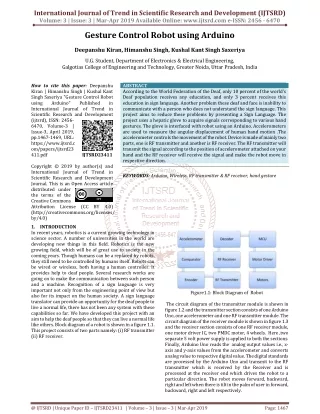
International Journal of Trend in Scientific Research and Development (IJTSRD) @ www.ijtsrd.com eISSN: 2456-6470 that the 555 IC got its name from these three 5 kΩ resistors ?Yellow: The comparator negative input is connected to the higher-reference voltage divider of 2⁄3 VCC (and "Control" pin), and comparator positive input is connected to the "Threshold" pin. ?Red: The comparator positive input is connected to the lower-reference voltage divider of comparator negative input is connected to the "Trigger" pin. ?Purple: An SR flip-flop stores the state of the timer and is controlled by the two comparators. The "Reset" pin overrides the other two inputs, thus the flip-flop (and therefore the entire timer) can be reset at any time. ?Pink: The output of the flip-flop is followed by an output stage with push-pull (P.P.) output drivers that can load the "Output" pin with up to 200 mA (varies by device). ?Cyan: Also, the output of the flip-flop turns on a transistor that connects the "Discharge" pin to ground. VIII. From the figure shows the Schematic Diagram of the project. The supply voltage of 230v is stepped down to 30v by the transformer. Rectifier gives a voltage of 9v DC. The equipment in the project works with 9v DC supply, So the voltage regulator 7809 is used. Schematic Diagram of developed model: 1⁄3 VCC, and Fig 5 Circuit Diagram for Automated Timer Socket Using Arduino to the Socket IX. The below figure 6 shows the developed “Automated timer socket using arduino UNO”. In this the when the project kit is ON it displays the time to set in hours and minutes by means by pressing S1 and S2 push buttons respectively which are fixed below the LCD display . After setting the time in display then press the S3 button to start the count set of the given time. The counting of given time is started by arduino UNO. RESULT: Fig 3 Logic Diagram of 555 Timer IC VI. When the automated system is introduced, the 555 timer is used for counting the time which is set on the screen to how much time is taken to disconnect the supply. After completion of time given in the display the timer gives the signal to relay. Then the circuit will be open circuited i.e, the supply to the socket is turned off .In this way the automation is done to on and off the supply to the socket without using manual on and off the power supply. VII. Block Diagram : The below figure 4 shows the Block Diagram of Automated Timer Socket Using Arduino EXISTING SYSTEM: Fig 6 Proto Type Model of Automated Timer Socket Using Arduino When the time count reaches zero automatically the power supply to the socket is disconnected by the relay. The instruction is given from arduino UNO to relay. This help to power off the supply automatically when we forget to switch off the supply when we keep the mobile or laptops in charging. This can prevent the damage of batteries or device. Fig 4 Block Diagram of Automated Timer Socket Using Arduino @ IJTSRD | Unique Paper ID - IJTSRD23157 | Volume – 3 | Issue – 3 | Mar-Apr 2019 Page: 1376
International Journal of Trend in Scientific Research and Development (IJTSRD) @ www.ijtsrd.com eISSN: 2456-6470 XII. We express our deep sense of gratitude and thanks to Dr. K. SATYANARAYANA, Vice Principal, Professor and H.O.D. of Electrical and Electronics Engineering, for having shown keen interest at every stage of development of our project work and for guiding us in every aspect. References [1]"Adruino UNO for beginners - Projects, Programming and Parts". makerspaces.com. February 2018. Mohammad Arif Hossain, Md. Nazmul Hasan , Modern Home Automation System Based On AVR Microcontroller, International Journal of Scientific & Engineering Research, Volume 5, Issue 1, January- 2014 1864 ISSN 2229-5518. Acknowledgment Retrieved 4 Fig 7 LCD Display Output of the Project with Mobile Charging Fig 7 shows the important feature of setting the timer count and the counting starts . And the mobile connected to the socket is charging perfectly. X. CONCLUSION: Now-a-days the mobile phones or any charging devices getting damage due to forget to switch off the supply after the mobile are fully charged. So by this project idea we can disconnect the power supply to the socket after fully charging of a device. By this the charging devices and mainly mobile phone are become to safe and become more durable for long time. XI. FUTURE SCOPE: We can extend this project by connecting any type of sensors like temperature sensor or light sensor we can operate the fans and lights for particular time period based on the surroundings temperature and light brightness. [2]Mustafa Saad, Hossam Abdoalgader, and Muammer Mohamed, Automatic Fan Speed Control System Using Microcontroller, 6th Int'l Conference on Electrical, Electronics & Civil Engineering (ICEECE'2014) Nov. 27- 28, 2014 Cape Town (South Africa) [3]Himani Goyal,Understanding of IC555 Timer and IC 555 Timer Tester,International Journal of Inventive Engineering and Sciences (IJIES) ISSN: 2319–9598, Volume-3 Issue-2, January 2015 [4]NE 555 timer datasheet,xx555 Precision Timers, texas instruments, SLFS022I –SEPTEMBER 1973–REVISED SEPTEMBER 2014. [5]Robert F. Coughlin, Fredrick F.Driscoll,operational amplifiers and linear integrated circuits(Prentice- Hallelectronics,2014). @ IJTSRD | Unique Paper ID - IJTSRD23157 | Volume – 3 | Issue – 3 | Mar-Apr 2019 Page: 1377