Download
1 / 6
60 likes | 86 Vues
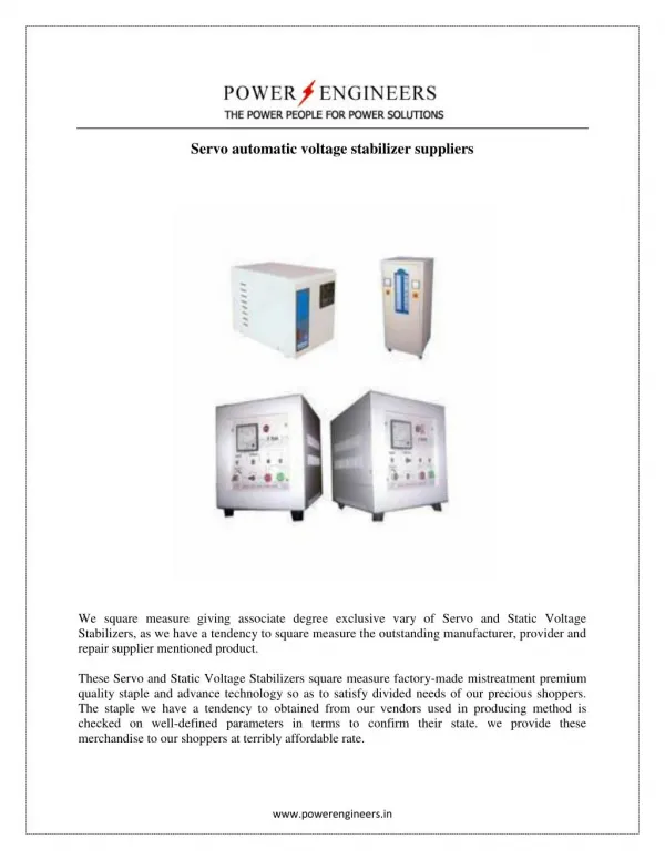
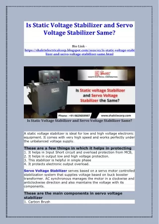
In Myanmar, voltage fluctuation always occurs in electrical supply system. Due to voltage fluctuation, life of electrical equipment consumed electricity is shorted really. To solve this problem, automatic voltage stabilizer is needed for domestic and industries. Both single phase and three phases are available. In this paper intend to known that automatic voltage stabilizer plays efficient role in all type of load i.e. resistive, inductive and capacitive loads. This paper present control circuit for automatic voltage stabilizer provides voltage comparator, relays and servo controlled motor that compare instantaneous input and output voltage. Automatic voltage stabilizer consists of two unit measuring unit and regulating unit. In this stabilizer, toroidal type variable autotransformer is used for regulating unit and electronic control circuit is used for sensing unit. Electromechanical or servo control system is used for measuring unit to sense the supply voltage. This electronic control circuit will operate within the fluctuation range from 120V to 250V.The rating of this automatic voltage stabilizer is 7kVA single phase and its frequency range is 50Hz. The output sensitivity is u00c2u00b11 . If input voltage is lower than 120V or higher than 250V, the system will be automatic shutdown. Hnin Hnin Aye "Design and Construction of Control System for Automatic Voltage Stabilizer" Published in International Journal of Trend in Scientific Research and Development (ijtsrd), ISSN: 2456-6470, Volume-3 | Issue-1 , December 2018, URL: https://www.ijtsrd.com/papers/ijtsrd19004.pdf Paper URL: http://www.ijtsrd.com/engineering/electrical-engineering/19004/design-and-construction-of-control-system-for-automatic-voltage-stabilizer/hnin-hnin-aye<br>

E N D
International Journal of Trend in Scientific Research and Development (IJTSRD) International Open Access Journal | www.ijtsrd.com ISSN No: 2456 - 6470 | Volume - 3 | Issue – 1 | Nov – Dec 2018 Design and Construction of Control System for Automatic Voltage Stabilizer Hnin Hnin Aye Department of Electrical Power Engineering, Technological University, Thanlyin, Myanmar ABSTRACT In Myanmar, voltage fluctuation always occurs in electrical supply system. Due to voltage fluctuation, life of electrical equipment consumed electricity is shorted really. To solve this problem, automatic voltage stabilizer is needed for domestic and industries. Both single phase and three phases are available. In this paper intend to known that automatic voltage stabilizer plays efficient role in all type of load i.e. resistive, inductive and capacitive loads. This paper present control circuit for automatic voltage stabilizer provides voltage comparator, relays and servo-controlled motor that compare instantaneous input and output voltage. Automatic voltage stabilizer consists of two unit; measuring unit and regulating unit. In this stabilizer, toroidal type variable autotransformer is used for regulating unit and electronic control circuit is used for sensing unit. Electromechanical or servo control system is used for measuring unit to sense the supply voltage. This electronic control circuit will operate within the fluctuation range from 120V to 250V.The rating of this automatic voltage stabilizer is 7kVA (single phase) and its frequency range is 50Hz. The output sensitivity is ±1%. If input voltage is lower than 120V or higher than 250V, the system will be automatic shutdown. Keywords: Voltage stabilizer, LM324, Relays, Controller Design, Performance Test and Results 1.INTRODUCTION: Servo controlled voltage stabilizer is a useful and effective device used to maintain a constant power supply. Voltage fluctuation is a common problem in Myanmar, which can cause damage in electronic devices used in home and in industries. To solve these appliances safe is to use voltage stabilizers. The automatic voltage stabilizers are widely used in industrial application to obtain the stability and good regulation for the sophisticated electrical and electronic equipments such as communication equipments and system, process controller, computer equipment etc [1]. Servo controlled is a closed loop systems for electric motors. The motor used in servo control is usually DC motor used in servo is also possible. The servo system uses a sensor to sense motor position/speed. Servo control has a feedback circuit which changes the drive power going to motor according the control input signals and signal from sensors[2]. There are various types of stabilizers available in market. Both single phase and three phases are available. The rating of this type of stabilizer is quite high and is more economical for high power rating .Based on the change in main voltage, the automatic voltage stabilizers increase or decreases the power supply to rectify the deviation and brings the power supply to normal level. Automatic voltage stabilizer provides a continuous monitoring of output voltage by means of an electronic control circuit that compares the instantaneous output voltage with the set value. Servo voltage stabilizer uses an advance electronic controlled servo controlled motor concept to govern a motorized variable autotransformer. Because of the motor involved, there is a small delay in voltage correction. However, output voltage accuracy is usually ±1% with input voltage change of ±50%. This stabilization method does not create interference or harmonics in the supply system. @ IJTSRD | Available Online @ www.ijtsrd.com | Volume – 3 | Issue – 1 | Nov-Dec 2018 Page: 381
International Journal of Trend in Scientific Research and Development (IJTSRD) ISSN: 2456-6470 2.Servo System Voltage Stabilizer In this journal, automatic voltage stabilizer consists of regulating unit and measuring unit. Fig 1 shown below are the block diagram and circuit diagram of the voltage stabilizer connected to an appliance or load. The stabilizers sizes generally with its rating, which is given in kVA. output Sensing unit input Relay Transformer Rectifier Motor Figure 1. Block diagram of servo controlled voltage stabilizer Output Relay RLY 2 250V 220V Output 220V 120V ~ 250V M Input 32V 24V 12V (1) Voltage sensing (2) Power supply for control circuitry (3) Power supply for d.c. motor 0V Figure 2.Schematic diagram of automatic voltage stabilizer The regulating unit consists of toroidal type variable autotransformer. The purpose of the regulating unit is that of acting under the signal from the measuring unit in such a manner as to correct the output voltage of the stabilizer, as near as possible, a constant or predetermined value. Measuring unit includes control circuit. The function of the measuring unit is that of detection a change in the input or output voltage of automatic voltage stabilizer and producing a signal to operate the regulating unit. Switch Limit 2200u C17 33R 0.22 M C18 R43 Relay 1 2k7 R25 10 NC R13 NO Q1 R 1N4148 D15 10R 10R 470R R11 Q2 2k7 R28 D14 14 9R 1k 7 8 360k R24 voltage On/Off 360k Under 10 9 3 4 R 360k R27 10 12 13 2 8R 6 5 5k1 5k1 Vcc R23 R26 C16, 220u 7k5 10k 18k 6R 7R 2k R21 2k2 2k 8k2 4k7 R19 VR2 R18 R22, 1k R17 470R R16 1k2 R20 33u 0.1 ZD4 9v1 5k1 R31 18k R32, Vss 1k470R 470R C3 33u C5 5k1 22u C15 R5 R29 33u 62k 270k R30, C4 C2 R33, S8050 Q5 0.1 R4 0.01 C8 33u C12 470R C14 12V 10k R34 33u C7 R3 R14 ZD2 33u C13 2 3 470R R15, 1 1 D13 12v ZD3 VR1 R2 10k 2k2 2k7 R1 S8550 R35 D10 1k 220u C6 D7 1N4007 ZD1 D11 Q4 Rly 2 39R R36 220u C1 D4 220u D3 1N4007 Delay Indication 33u C11 C9 5k1 R38 D8 + D1 D2 10k Rly 1 R37 Indication 51R R39 5D D6 Power D9 220u C10 24V 12V 32V 0V Figure3. Overall Circuit Diagram of AVS @ IJTSRD | Available Online @ www.ijtsrd.com | Volume – 2 | Issue – 6 | Sep-Oct 2018 Page: 382
International Journal of Trend in Scientific Research and Development (IJTSRD) ISSN: 2456-6470 Overall circuit diagram of control circuit for AVS is shown in fig: 2. Transformer steps down the AC source voltage to 12V. Then, the transformer output is rectified by bridge rectifier. The rectifier output voltage is filtered by capacitor. In this circuit, LM324 is used as comparator and indicator. The non- inverting input (-Vin) the op-amp is greater than the inverting input (-Vin) the op-amp is ON-state. At normal condition, positive voltage sensing only. If VR1 is adjusted so that when output AC voltage is 220V, the op-amp output is zero. Op-amp (3) is used for over-voltage condition. It is connected as voltage comparator. When transistor Q2 base receives forward bias and Q2goes ‘ON’ motor runs in the direction to raise voltage. When transistor Q1 base is forward biased and Q1goes ‘ON’ motor runs in the other direction to lower voltage. After the present time, op- amp output swings positive and release the relay. The control system is automatically shut down when the voltage fluctuation is lower than 120V and higher than 250V. 3.Design Consideration Power supply system is an essential part of each electronic system from simplest to the most complex. Input voltage supply is 220V AC supply. Automatic voltage stabilizer control system is based on mainly control circuit. Applying Kirchhoff’s Current Law (KCL), I +I =I + I I +I I V -V V -V V -V + = R R R V The open loop gain, A = = V 4.RESULTS AND DISCUSSION In this section the results obtained from the design calculation of stabilizer controller. There are three conditions by the unstable input supply. 4.1Normal Condition The parameter of Op-amp 2, V2 1 2 f b 1 2 f i1 0 1 2 2 i1 1 2 f V 0 0 V -V id i2 i1 V R V R V =-R + 1 2 0 f 1 2 R6 R10 V1 Vout R7 6 R9 7 2 5 R8 Figure6. Circuit Diagram of Op-amp 2 of LM324N Op-amp (2) is connected as a summing amplifier. Applying KCL, At pin 6 and virtual ground concept = - ( + ) R R R V1 is positive and represents the sample of output a.c voltage. V2 is fixed negative voltage: it acts as reference voltage. Assume, V1=9.87V, V2=-5.48V Apply the KCL, V V + =0 R R 5.48R7 = 9.87R6 If R6=10k , R7=18k The standard of R6=10k and R7=18k And then, I6 = 2 V R I7 = 1 V R If AC output voltage is 1% change, V1=0.999.87=9.77V V V V = - ( + ) R R R 9.77 5.48 V = ( - + ) R 18k 10k Out 4 { Out 1 Input 1{ 14 1 2 - - 13 V V V Input 4 4 out 1 2 1 + + 3 4 5 12 11 10 7 6 Vcc VEE, GND { Out 3 { + + 10 Input 2 2 - 3 Input 3 - 6 9 8 7 Out 2 Figure4. Diagram of Pin Function of LM324 In figure 3, LM324 is a 14 pin IC consisting of four independent operational compensated in a single package. Op-amp is high gain electronic voltage amplifier with differential input and usually, a single-ended output. The output voltage is many times higher than the voltage difference between input terminals of an op-amp. ( In normal condition, Vout =0 ) 1 2 amplifiers (op-amp) 7 6 = -5.42 10k = -0.55 mA = 9.87 6 Rf 18k = 0.55 mA If 7 R1 I1 Ib +Vcc V1 Vout Vi1 out 1 2 V2 I2 -VEE 10 7 6 R2 Figure5. Summing amplifier of op-amp out 10 @ IJTSRD | Available Online @ www.ijtsrd.com | Volume – 2 | Issue – 6 | Sep-Oct 2018 Page: 383
International Journal of Trend in Scientific Research and Development (IJTSRD) ISSN: 2456-6470 VR2 is adjusted so that at normal condition there is about +7.35 at pin 10. At normal condition, op-amp output is negative because 8.08>7.35V When output voltage increase to 242V, Pin 10 voltage = 8.085V Since 8.085V > 8.08V, op-amp output goes positive and drives the relay. Assume I=1mA through voltage divider R17, R18, R19, R20. R17 = 1.02 k Apply by KVL, IR18+IR19+IR20=8.08V R18 + R19 + R20 = 8.08 1m 8.3-6.5 R = 1m By Ohm’s Law, 1.23 R =1m = 1.2 k R18 + R19 + R20=8.08k R19=5.08k The standard value of R17=1k, R18=2k, R19=4.7k and R20=1.2k. In this circuit, R23=5.1k, and R24=360k is used for prevent short circuit. Assume, I=5mA for LED lamp 12 R = = 2.4k 5m The standard value of R25= 2.7k 4.3 Under-Voltage Condition The parameter of Op-amp 4, +9.87V -6 V = 5.22×10 R Assume motor pick-up voltage =2V R10=382k The standard value of R10=382k In this research, R8=7.5k and R9=1k are chosen. When V1 falls below normal, inverting input becomes negative and op-amp output swings positive and drives the motor in the direction to increase output voltage. If V1 increase above normal, the process is reverse order. time delay is calculated by the equation, V = V.e R=9.642k, C=33F, V=12V, Vc=1.23V 1.23 ln( ) 13 t = 0.7sec 4.2Over-Voltage Condition The parameter of Op-amp 3, out 10 t -t c = 8.08 k t − = = 1.8 k 18 20 R21 R24 I=1mA R23 10 VR2 D15 R17 8 3 9 R18 R25 ZD4 25 R19 R22 C16 R20 Figure7. Circuit Diagram of Op-amp 3 of LM324N From normal condition, node voltage V=9.87V Assume, the non-inverting input (pin 9) = 8.08V (fixed voltage) Assume, I=0.8mA Non-inverting input (pin10) is fed from voltage sensing supply through voltage divider R21, VR2, R22 Apply by KVL, IR21+IVR2+IR22=9.87V R21+VR2+R22= 12.34k By Ohm’s Law, V=IR 9.87-8.3 R = 0.8m 8.3-6.5 V = 0.8m R21+VR2+R22= 12.34k R22=8.2 The standard value of R21=2k, VR2=2.2k and R22=8.2k I R21 +9,1V VR2 R27 R17 +7.35V R26 12 D14 R18 ZD4 9v1 4 13 +6.03V R28 R19 R22 C16 = 1.96k R20 21 = 2.2k Figure8. Circuit Diagram of Op-amp 4 of LM324N Under-voltage condition circuit is almost same as over-voltage condition except that op-amp inputs are interchanged. R 2 @ IJTSRD | Available Online @ www.ijtsrd.com | Volume – 3 | Issue – 1 | Nov-Dec 2018 Page: 384
International Journal of Trend in Scientific Research and Development (IJTSRD) ISSN: 2456-6470 Reference voltage at non-inverting input is 6.03V Assume, fixed voltage V=6.03V and I=1mA 9.1-8.08 R = = 1.02 k 1m R17+R18= 3.07k R18=2.07k Apply by KVL, IR18+IR19+IR20 = 8.08V R18+R19+R20=8.08k R19+R20=6.03k Assume time delay voltage=1.23V By Ohm’s Law, V= IR 1.23 R = = 1.23 k 1m R18+R19+R20 = 8.08k R19 = 4.78k The standard value of R17=1k, R18=2k, R19=4.7k and R20 = 1.2k. In this circuit, R26=5.1k and R27=360k is used for prevent short circuit. Assume, I=5mA for LED lamp 12 R = = 2.4 k 5m The standard value of R25=2.7k If a.c output voltage falls below 180V, pin 13 voltage falls below +6.03 V and op-amp output goes positive. When output voltage decreases to 180.4V, pin 12 voltage= × 180.4 = 6.02V 220 Since 6.02 < 6.03, op-amp output goes positive and drives the relay. A variable resistor VR2 is used so that the user can adjust the voltages settings at the desired position. In this case, over-voltage setting 240V and under- voltage setting 180V. time delay is calculated by the equation, V = V.e R=9.642k, C=33F, V=12V, Vc=1.23V 1.23 ln( ) 13 t = 0.7sec 28 17 7.35 20 t -t c t − = Table1. Results for low voltage up to -45% Input voltage Output voltage Difference voltage Clockwise direction Linear Displacement 210 220 -10 200 220 -20 190 220 -30 180 220 -40 170 220 -50 160 220 -60 150 220 -70 140 220 -80 130 220 -90 120 220 -100 13.46° 26.92° 40.38° 53.84° 67.3° 80.76° 94.22° 107.68° 121.14° 134.6° 25.841 51.683 77.524 103.365 129.207 155.048 180.89 206.731 232.572 258.413 Table 2. Results for high voltage up to +13% Input voltage Output voltage Difference voltage Anticlockwise direction Linear displacement 230 220 +10 240 220 +20 250 220 +20 13.46° 26.92° 40.38° 25.841 51.683 77.524 If the supply voltage is lower than 120V and more than 250V, the supply of the motor will be cut out. After that the relay will cut out the supply. So, automatic voltage stabilizer will not produce the power supply without being 220 stable voltage. Fig 11 shows normal condition with digital meter (yellow for input and red for output). Figure 9.Photo showing 7kVA, Automatic Voltage Stabilizer Control System at Normal Condition @ IJTSRD | Available Online @ www.ijtsrd.com | Volume – 3 | Issue – 1 | Nov-Dec 2018 Page: 385
International Journal of Trend in Scientific Research and Development (IJTSRD) ISSN: 2456-6470 Fig.10 shows that under voltage condition, the input voltage of the stabilizer is lower than output voltage, the sensing circuit is unbalanced that and the op-amp output is positive. The motor rotates clockwise direction as to increase the stabilizer output voltage to 220V.By testing digital meter (yellow for input and red for output). direction. In this research, the input voltage fluctuation can be with stand 120V and 250V for single-phase 7kVA. The control circuit components are available in local market. So the circuit component can be replaced easily when they are damaged. This automatic voltage stabilizer is very suitable and economical for all electrical equipments. This automatic voltage stabilizer is very convenience and economic for domestics and industries. So, automatic voltage stabilizer having with these conditions will offer the stable output voltage or stable output voltage for all electrical equipments and will improve productivities and reduce downtime. 6.ACKNOWLEDGMENTS The author is deeply grateful to her dissertation superior and co-supervisor. The author also thanks to all teachers at Technological University (Thanlyin) and all who provided her with necessary assistance for this paper. The author wishes to express her guidance to all persons who helped directly or indirectly towards the successful completion of paper. Finally, the author wishes to express her special thanks to her parents for their support and encouragement to attain her destination without any trouble. 7.REFERENCES 1.Servo controlled voltage stabilizer introduction, amjadeeeseminars blogspot, 1st December 2012. 2.P. Eswaran, “Design of fuzzy logic controller for customized servo voltage stabilizer” , 2nd International Conference on Electronic and Communication Systems, 26-27 February 2015, pages 103-106. 3.Instruction manual for servo-controlled stabilizer, Servel Electronics Private Limited. 4.McGrana Ghan M. F., Mueller D. R. and Samotyi m. J. (1993), “Voltage Sag in Industrial Systems,” IEEE Transactions on Industry Applications, Vol.29, pp.397-403. 5.M. Htay and K. San Win, “Design and Construction of an Automatic Voltage Regulator for Diesel Engine Type Stand-alone Synchrous Generator,” PP.652-658 Figure 10.Photo showing 7kVA, Automatic Voltage Stabilizer Control System at under-voltage Condition Fig.11 shows that over voltage condition, the input voltage of the stabilizer is higher than output voltage, the sensing circuit is unbalanced that and the op-amp output is positive. The motor rotates anti-clockwise direction as to decrease the stabilizer output voltage to 220V. By testing digital meter (yellow for input and red for output) Figure 11.Photo showing 7kVA, Automatic Voltage Stabilizer Control System at over-voltage Condition 5.CONCLUSION In this circuit when the input voltage is lower than 220V, the relay starts energized and the motor rotates the clockwise direction. And then the input voltage is higher than 220V, the motor rotates the anticlockwise @ IJTSRD | Available Online @ www.ijtsrd.com | Volume – 3 | Issue – 1 | Nov-Dec 2018 Page: 386