Download
1 / 3
30 likes | 43 Vues
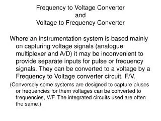
Nowadays solid state technology, engine driven generators, as an aircraft power system, supply 400Hz elecctrical loads for more efficient and effectiveness. The system produces stable and constant 400Hz from variable input frequency of DC link converter. Constant speed drive was momentously replaced by means of providing a constant frequency power supply of static frequency converter. Furthermore, easiness of repair and replacement, reduction in servicing needs, and the ability to locate the components of the electrical system are extended effectiveness of static frequency converter. Research demonstrates design consideration process of the 400Hz converter control system with relaible output power effectively. Soe Winn | Hla Yin Htwe | Hla Hla Naing "Design and Performance Analysis of 400Hz Static Frequency Converter" Published in International Journal of Trend in Scientific Research and Development (ijtsrd), ISSN: 2456-6470, Volume-3 | Issue-5 , August 2019, URL: https://www.ijtsrd.com/papers/ijtsrd26701.pdf Paper URL: https://www.ijtsrd.com/engineering/electrical-engineering/26701/design-and-performance-analysis-of-400hz-static-frequency-converter/soe-winn<br>

E N D
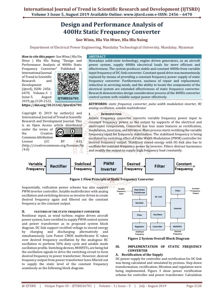
International Journal of Trend in Scientific Research and Development (IJTSRD) Volume 3 Issue 5, August 2019 Available Online: www.ijtsrd.com e-ISSN: 2456 – 6470 Design and Performance Analysis of 400Hz Static Frequency Converter Soe Winn, Hla Yin Htwe, Hla Hla Naing Department of Electrical Power Engineering, Mandalay Technological University, Mandalay, Myanmar How to cite this paper: Soe Winn | Hla Yin Htwe | Hla Hla Naing "Design and Performance Analysis of 400Hz Static Frequency Converter" Published in International Journal of Trend in Scientific Research and Development (ijtsrd), ISSN: 2456- 6470, Volume-3 | Issue-5, August 2019, pp.2120-2122, https://doi.org/10.31142/ijtsrd26701 Copyright © 2019 by author(s) and International Journal of Trend in Scientific Research and Development Journal. This is an Open Access article distributed under the terms of the Creative Commons Attribution License (CC (http://creativecommons.org/licenses/by /4.0) ABSTRACT Nowadays solid-state technology, engine driven generators, as an aircraft power system, supply 400Hz elecctrical loads for more efficient and effectiveness. The system produces stable and constant 400Hz from variable input frequency of DC-link converter. Constant speed drive was momentously replaced by means of providing a constant frequency power supply of static frequency converter. Furthermore, easiness of repair and replacement, reduction in servicing needs, and the ability to locate the components of the electrical system are extended effectiveness of static frequency converter. Research demonstrates design consideration process of the 400Hz converter control system with relaible output power effectively. KEYWORDS: static frequency converter, pulse width modulation inverter, RC analog oscillation, astable multivibrator I. INTRODUCTION Astatic frequency converter converts variable frequency power input to constant frequency power as the output by supports of the electrical and electronics components. Converter has four main features as rectification, modulation, inversion, and filtration. Main process starts rectifying the variable frequency input for frequency stabilization. The stabilized frequency is being oscillated by switching effect of Pulse Width Modulation (PWM) controller for desired frequency output. Stabilized stored energy with DC-link also has to oscillate for constant frequency power by inverter. Filters distract harmonics and modify the output to supply high frequency load constantly. IJTSRD26701 BY 4.0) Figure 1 Flow Principle of Static Frequency Converter Sequentially, reification power scheme has also support PWM inverter controller. Astable multivibrator with analog oscillation and switching devices as inverter drives to create desired frequency again and filtered out the constant frequency as the constant output. II. FEATURES OF THE STATIC FREQUENCY CONVERTER Nonlinear input, as wind turbine, engine driven aircraft power system, have rectified to supply PWM control system and power transformer as in proposed system block diagram. DC link support rectified voltage to stored energy by charging and discharging simultaneously. Low Power CMOS multivibrator IC takes over desired frequency oscillation by the analogous RC oscillation to perform 50% duty cycle and astable mode oscillation profile. Switching devices, MOSFETs, are being fed the oscillation signals to drive the switching circuit to form desired frequency in power transformer. However, desired frequency output from power transformer have filtered out to supply the static level of the constant frequency seamlessly as the following block diagram. alternatively and Figure 2 System Overall Block Diagram IMPLEMENTATIONOFSTATICFREQUENCY CONVERTER A.Rectification of the Supply DC power supply for controller and rectification for DC link was being calculated and simulated by proteus. Step down transformation, rectification; filtration and regulation were being implemented. Figure 3 show power rectification scheme for controller and power transformer. Calculation III. @ IJTSRD | Unique Paper ID – IJTSRD26701 | Volume – 3 | Issue – 5 | July - August 2019 Page 2120
International Journal of Trend in Scientific Research and Development (IJTSRD) @ www.ijtsrd.com eISSN: 2456-6470 and evaluation of transformer is out of the scope and have used two winding step down transformer with rating of 220/24V, primary and secondary, inductances and resistances are 1H and 1mΩ with ideal coupling factor. Uncontrolled rectifier is being used 4 numbers of 1N4007 take over full wave bridge rectification. Ripple cancellation feature is implemented by 1mF electrolyte capacitor. Stabilized output is evaluated and being used 12V battery as a DC link energy storage device. Voltage regulator as LM7805 IC with reliable ventilation system, heat sink with suitable area, should be used as a linear regulator for stable input to control system. Power transformer is supplied directly from DC link battery with PWM inverter. modulation signals for oscillation power switching of power transformer. Mid-range Mosfet IRFZ44Es are being deployed as frequency switching device for PWM inverter switching controller to achieve desired frequency oscillation. Advantageous of IRFZ44E are its fast switching and dynamic dv/dt rating and also have good switching performance even high temperature. Figure5 High Frequency Switching Devices Scheme Two bleeder resistors are used to limit the control current to activate the positive and negative sequence alternatively. According to the characteristic of IRFZ44E, 100KΩ could limit IGSS would not be greater than maximum drain to source leakage current with the gate to source voltage, VGS = ±20V. IRFZ44E have 60ns rise time, ‘Tr’ and 70ns fall time, ‘Tf’ according to datasheet. At the desired frequency 400Hz, ‘f’, the time taken for each positive and negative half cycle is, T = 1/f = 2.5ms. Sinusoidal alternating voltage must be 50% duty cycle and could yield positive region on-time, ‘Ton’, and off-time, ‘Toff’, negative region on-time, ‘Ton’, and off-time, ‘Toff’ all are the same length, but symmetrically. Therefore, T = Ton + Toff + Tr + Tf, could determine on and off duration of the desired frequency. Ton = Toff = (T – Tr – Tf)/2 = 1.2499ms. Calculation have 0.1us deviation and during acceptable limit. Stabilized power from DC link connects directly to power transformer for power alternation. Power quality is being acceptable without capacitive filtering on the primary side of the transformer. Rating of 12/220V center-tap step-up transformer must be used to achieve each half cycle oscillation alternatively. The high voltage winding characteristics are 1H inductance and 15Ω resistance. Low voltage windings have 0.1Ω copper resistance each and coupling coefficient is assumed as 0.98. Figure3 Power Rectification Scheme B.Reference Frequency Oscillation Linear Regulator LM7805 regulated power to supply CMOS IC CD4047 which was being used for frequency oscillator and RC analog oscillation method drives the desired frequency 400Hz. CD4047 is low power CMOS IC with monostable/astable multivibrator and configured as astable function with 50% duty cycle. Trial and error method was used for R1C1 evaluation by using the frequency modulation formula of astable multivibrator, T = 4.4 R1C1 which drive to calculate f*R1C1 = 0.227. 100KΩ and 0.022uF or 25KΩ and 20.2nF can use to retrieve 400Hz reference frequencies. Error accuracy is acceptable and Resistor, Capacitor evaluation is being implemented. Figure4 Analog RC Oscillation Scheme Astable mode pin assignments for CD 4047 IC, figure 4, are as follows: Pin 4, 5 and 6 as signals input terminals, Pin 8, 9, 12 as neutral or negative rail, Pin 10, 11 as positive and negative half each oscillators, 1, 2 and 3 as analog oscillation component, RC, terminals. Pin 13 as NC and Pin 7 and 14 are power input terminals. According to the performance analysis result, frequency deviations tolerance is ±1% (397Hz-403Hz) accurate level. C.PWM Inverter Switching Pin 10 and 11, CD 4047 CMOS IC, provide astable mode, 50% duty cycle, positive and negative half pulse-width Figure6 PWM Input and Filterless Output Waveform Although power transformer output is acceptable modified sine wave, output waveform has harmonics, dc-offset and notching which affect the output power quality. Figure 6 @ IJTSRD | Unique Paper ID – IJTSRD26701 | Volume – 3 | Issue – 5 | July - August 2019 Page 2121
International Journal of Trend in Scientific Research and Development (IJTSRD) @ www.ijtsrd.com eISSN: 2456-6470 shows input output waveform of the power transformer power quality. D.Constant Frequency Stabilization Finally, oscillating transformer provides desired and stable frequency with acceptable accuracy by filtering the harmonics and cancelling the dc offset with filters. Passive filter component, 470nF capacitor is being cancelled out the harmonics and notching by installing in series of the power transformer. Ripple cancellation filter, 1uF capacitor is being installed in parallel to boost the offset for waveform smootheness. V. Efficiency of DC power supply is acceptable enough to drive the controller and to supply the oscillation transformer. Duty cycle implementation of CD4047 CMOS is being set up as astable. According to analog RC oscillation, pure passive device, resistor is less flexible than temporarily energy stored device, capacitor. Switching time and loss is acceptable as well for 400Hz oscillation for the simulation over time domain. VI. CONCLUSION Static frequency converter is widely use device as an airplane power system with much advantageous, as which could reduce weight of the devices and better reliability. Appendix 400Hz RC analog oscillation evaluation table is being provided. Resistor Period DISCUSSION AND EVALUATION Figure7 Capacitive Filters and Waveform Callibration Frequency Frequency counter and digital oscilloscope were being used to implement the result effectively. IV. SIMULATION AND RESULT EVALUATION Following figure shows final evaluation result and overall configuration of the research. Power rectification is completed by stepping down the voltage by transformer, full wave diode bridging, capacitive ripple cancellating and voltage regulating by linear regulator. RC analog oscillation circuit drives creating reference oscillating frequency, 400Hz by CD 4047 CMOS IC as astable multivibrator. Frequency singal supports oscillating transformer for power oscillation by using bleeding resistors and IRFZ44E switching Mosfets. 28.30 k 2.740 ms 365.0 Hz 27.27 k 2.54 ms 378.8 Hz 26.45k 2.56 ms 390.6 Hz 26.09 k 2.52 ms 396.0 Hz 25.83 k 2.5 ms 400.0 Hz 25.59k 2.48 ms 403.2 Hz 24.76 k 2.39 ms 416.7 Hz 24.14k 2.34 ms 427.4 Hz Acknowledgment Author would like to acknowledge, Minister of Education, Rector of Pyay Technological University, faculties of Department of Electrical Power Engineering, colleagues from Power Electronics and Device Control Engineering Division, Parents, wife and son. References [1]Zin Mar Soe, Mar.2017. Design and Implementation of Static Frequency Converter for Aircraft Power System, ME Thesis, Mandalay Technological University. [2]Design and Simulaltion of 80KHz High Frequency Converter using CD4047 CMOS, ME Thesis, Pyay Technological University Figure8 Desired Frequency 400Hz Simulation Power transformer oscillate the power and desired frequency but with waveform distortion. Capacitive filters tuned the waveform to evaluate finally result. [3]Akshata A. Supekar, P.M. Kurulkar, K.P.rathod, “Design and Simulation of Power Conditioning System(PCS) for Defence Applications,” 12th IEEE INDICON 17-20 Dec.2015, New Delhi, India. [4]Bettina Rubino;LuigiAbbatelli; Giuseppe Catalisano; Simone Buonomo; “1200V SiC MOSFET and N- off SiC JFET performences and driving in high power-high frequency power converter; Nurnberg, PCIM 2013 [5]IC CD 4047IC Datasheet acquired from Harris Semiconductor SCHS044C – Revised September 2003 [6]Kaushik, R. 2002. “Power Electronic Handbook”. Sohail Anwar© by CRC Press LLC. Figure9 Frequency Oscillations by CD4047 @ IJTSRD | Unique Paper ID – IJTSRD26701 | Volume – 3 | Issue – 5 | July - August 2019 Page 2122