Download
1 / 5
60 likes | 79 Vues
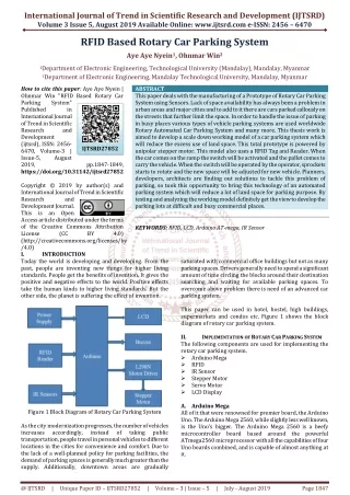
Radio Frequency Identification RFID technology is widely used in various applications such as attendance system, tracking system, monitoring system or parking system. In this paper, the Parking Lot Security System using RFID technology and embedded technology is presented. In conventional parking system, manual entrance system is applied that permission must be requested from the security guard to access the premise. Therefore, a security guard has to be hired to monitor the premise. In addition, the security guards need to monitor all movement of the vehicle that enters or leave the premise. As a result, the unauthorized vehicle can easily access the premise. To address this problem, the proposed system which can control a vehicle's movement that enters or leave the specific area or place by scanning the RFID tag has been implemented. The potential benefit is it can improve security for both security guards and users. Besides that, this parking system can facilitate access control for users and improve traffic flow and reduce traffic jams. Dr. Thida Aung "Parking Lot Security System using RFID Technology" Published in International Journal of Trend in Scientific Research and Development (ijtsrd), ISSN: 2456-6470, Volume-3 | Issue-5 , August 2019, URL: https://www.ijtsrd.com/papers/ijtsrd26512.pdf Paper URL: https://www.ijtsrd.com/engineering/electronics-and-communication-engineering/26512/parking-lot-security-system-using-rfid-technology/dr-thida-aung<br>

E N D
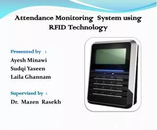
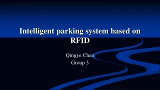
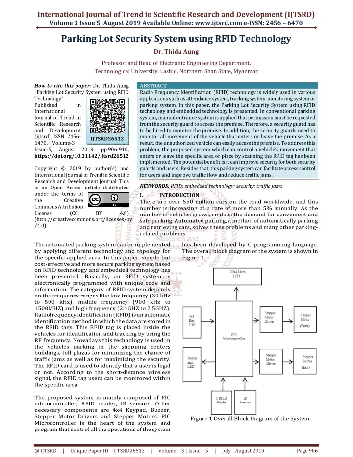
International Journal of Trend in Scientific Research and Development (IJTSRD) Volume 3 Issue 5, August 2019 Available Online: www.ijtsrd.com e-ISSN: 2456 – 6470 Parking Lot Security System using RFID Technology Dr. Thida Aung Professor and Head of Electronic Engineering Department, Technological University, Lashio, Northern Shan State, Myanmar How to cite this paper: Dr. Thida Aung "Parking Lot Security System using RFID Technology" Published in International Journal of Trend in Scientific Research and Development (ijtsrd), ISSN: 2456- 6470, Volume-3 | Issue-5, August 2019, https://doi.org/10.31142/ijtsrd26512 Copyright © 2019 by author(s) and International Journal of Trend in Scientific Research and Development Journal. This is an Open Access article distributed under the terms of the Creative Commons Attribution License (CC (http://creativecommons.org/licenses/by /4.0) The automated parking system can be implemented by applying different technology and topology for the specific applied area. In this paper, simple but cost-effective and more secure parking system based on RFID technology and embedded technology has been presented. Basically, an RFID system is electronically programmed with unique code and information. The category of RFID system depends on the frequency ranges like low frequency (30 kHz to 500 kHz), middle frequency (900 kHz to 1500MHZ) and high frequency (2.4GHZ to 2.5GHZ). Radiofrequency identification (RFID) is an automatic identification method in which the data are stored in the RFID tags. This RFID tag is placed inside the vehicles for identification and tracking by using the RF frequency. Nowadays this technology is used in the vehicles parking in the shopping centers buildings, toll plazas for minimizing the chance of traffic jams as well as for maximizing the security. The RFID card is used to identify that a user is legal or not. According to the short-distance wireless signal, the RFID tag users can be monitored within the specific area. The proposed system is mainly composed of PIC microcontroller, RFID reader, IR sensors. Other necessary components are 4x4 Keypad, Buzzer, Stepper Motor Drivers and Stepper Motors. PIC Microcontroller is the heart of the system and program that control all the operations of the system ABSTRACT Radio Frequency Identification (RFID) technology is widely used in various applications such as attendance system, tracking system, monitoring system or parking system. In this paper, the Parking Lot Security System using RFID technology and embedded technology is presented. In conventional parking system, manual entrance system is applied that permission must be requested from the security guard to access the premise. Therefore, a security guard has to be hired to monitor the premise. In addition, the security guards need to monitor all movement of the vehicle that enters or leave the premise. As a result, the unauthorized vehicle can easily access the premise. To address this problem, the proposed system which can control a vehicle’s movement that enters or leave the specific area or place by scanning the RFID tag has been implemented. The potential benefit is it can improve security for both security guards and users. Besides that, this parking system can facilitate access control for users and improve traffic flow and reduce traffic jams. KEYWORDS: RFID; embedded technology; security; traffic jams I. INTRODUCTION There are over 550 million cars on the road worldwide, and this number is increasing at a rate of more than 5% annually. As the number of vehicles grows, so does the demand for convenient and safe parking. Automated parking, a method of automatically parking and retrieving cars, solves these problems and many other parking- related problems. has been developed by C programming language. The overall block diagram of the system is shown in Figure 1. IJTSRD26512 pp.906-910, BY 4.0) Figure 1 Overall Block Diagram of the System @ IJTSRD | Unique Paper ID – IJTSRD26512 | Volume – 3 | Issue – 5 | July - August 2019 Page 906
International Journal of Trend in Scientific Research and Development (IJTSRD) @ www.ijtsrd.com eISSN: 2456-6470 II. To get started with RFID-based car parking system, the car owner has to first register the car with the parking owner and get the RFID tag. The incoming car drivers will be provided with an RFID card. The car parking owner must keep the ID of RFID card with a password and there is no limit quantity for this case. RFID reader controlled with PIC is fixed at the entrance gate to which the card bearing cars will enter. When the car reaches the gate, the card will be placed on the reader. As soon as the RFID tag is read by the reader, the system automatically reads the specified ID number from the RFID tag. If the card is correct, the gate-rod will be lifted (open) by a motor controlled with PIC microcontroller to allow the car inside the parking area. At the existing gate, two IR sensors are fixed to detect the body of the car. Only then, when the car reaches the exit gate, the gate-rod will be lifted (open) by a motor microcontroller. The system also offers the facility to recharge the amount for each RFID tag. No manual processing is involved and in addition, the system provides security. The flowchart of the operation of the system is shown in Figure 2. OPERATION OF THE SYSTEM III. A.Arduino UNO-R3 It's an open-source physical computing platform based on a simple microcontroller board and a development environment for writing software for the board. Arduino can be used to develop interactive objects, taking inputs from a variety of switches or sensors, and controlling a variety of lights, motors, and other physical outputs An Arduino is a tiny computer that you can program to process inputs and outputs going to and from the chip. It is connected to PC using the USB cable. It is an open-source electronics prototyping platform based on flexible, easy to use hardware and software. It„is intended for artists, designers, hobbyist and engineers. Arduino can sense the environment by receiving input from a variety of sensors and can affect its surroundings by controlling lights, motor and other actuators. The microcontroller on the board is programmed using the Arduino programming language. HARDWARE COMPONENTS controlled with PIC Figure 3. Arduino UNO-R3 B.PIC Microcontroller PIC is a family of microcontrollers made by Microchip Technology, derived from the PIC1650 originally developed by General Instrument's Microelectronics Division. The name PIC initially referred to Peripheral Interface Controller then it was corrected as Programmable Computer. Early models of PIC had read-only memory (ROM) or field-programmable EPROM for program storage, some with provision for erasing memory. All current models use flash memory for program storage, and newer models allow the PIC to reprogram itself. Program memory and data memory are separated. Data memory is 8-bit, 16-bit, and, in the latest models, 32-bit wide. Program instructions vary in bit-count by family of PIC, and maybe 12, 14, 16, or 24 bits long. The instruction set also varies by model, with more powerful chips adding instructions for digital signal processing functions.Today, a huge variety of PICs are available with various onboard communication modules, UARTs, motor control kernels, etc.) and program memory from 256 words to 64K words and more. PIC 16F877 is chosen as the main controller for this system because it meets the requirements of the system and it has rich features. PIC 16F877 is the mid-range pic and it has 40 pins. Intelligent peripherals (serial Figure2. Flow Chart of the Operation of the System @ IJTSRD | Unique Paper ID – IJTSRD26512 | Volume – 3 | Issue – 5 | July - August 2019 Page 907
International Journal of Trend in Scientific Research and Development (IJTSRD) @ www.ijtsrd.com eISSN: 2456-6470 directly related to the direction of motor shafts rotation. The speed of the motor shafts rotation is directly related to the frequency of the input pulses and the length of rotation is directly related to the number of input pulses applied. One of the most significant advantages of a stepper motor is its ability to be accurately controlled in an open-loop system. Open-loop control means no feedback information about the position is needed. This type of control eliminates the need for expensive sensing and feedback devices such as optical encoders. Figure4. PIC 16F877 Microcontroller C.RFID Reader The RFID reader requires 5V supply (it can be supplied from the same supply as PIC. This can read 125 kHz frequency and it is compatible with most kinds of RF cards. It can be connected directly to PIC microcontroller using the USART module to give 9600bps TTL and RS232 output. RDM6300 125 KHz card mini-modules is designed for reading code from 125KHz/ 134.2KHz card compatible read-only tags and read/write a card. It can be applied in office/home security, personal identification, access interactive toy and production control systems etc. RDM6300 Series non-contact RFID module, use the advanced RF receiving circuit and embedded MCU design, combing with high efficient decoding algorithm, to finish the data receive of EM4100 and all the compatible cards. This is a very popular RFID card read module for microcontroller users, it can read the 125K EM4100 series RFID card. This module is easy to use, serial port connects to microcontroller MCU after power-up, when the RFID card enters into card reading range, this module will send the card number to the microcontroller by UART. control, and forgery, Figure 6. Stepper Motor E.IR Sensor Module IR sensor is a very popular sensor, which is used in many applications in electronics like it is used in Remote control system, Motion detector, Product counter, Line follower Robots, Alarms etc. Infrared Obstacle Sensor Module has a built-in IR transmitter and IR receiver that sends out IR energy and looks for reflected IR energy to detect the presence of any obstacle in front of the sensor module. The module has an onboard potentiometer that lets the user adjust detection range. The sensor has a very good and stable response even in ambient light or in complete darkness. The Obstacle Avoidance Sensors usually come in two types - with 3 and 4 pins. The 3 pin version does not have the ability to be enabled/ disabled. The 4 pin version has optional Enable pin. Figure 5.RFID RDM3600 D.Stepper Motor A stepper motor is an electromechanical device which converts electrical pulses into discrete mechanical movements. The shaft or spindle of a stepper motor rotates indiscrete step increments when electrical command pulses are applied to it in the proper sequence. The motors rotation has several direct relationships to these applied input pulses. The sequence of the applied pulses is Figure.7 IR Sensor F.20X4 LCD Display A Liquid Crystal Display (LCD) is an electronic device that can be used to show numbers or text. There are two main types of LCD display, numeric @ IJTSRD | Unique Paper ID – IJTSRD26512 | Volume – 3 | Issue – 5 | July - August 2019 Page 908
International Journal of Trend in Scientific Research and Development (IJTSRD) @ www.ijtsrd.com eISSN: 2456-6470 displays (used in watches, calculators etc.) and alphanumeric text displays. The LCD screen is an electronic display module and finds a wide range of applications. An LCD display modules are preferred over seven segments and other multi segment LEDs. The reasons being: LCDs are economical; easily programmable; have no limitation of displaying special & even custom characters (unlike in seven segments), animations and so on. A 20x4 LCD means it can display 20 characters per line and there are 4 such lines. In this LCD each character is displayed in the 5x7 pixel matrix. This LCD has two registers, namely, Command and Data. The command register stores the command instructions given to the LCD. A command is an instruction given to LCD to do a predefined task like initializing it, clearing its screen, setting the cursor position, controlling display etc. The data register stores the data to be displayed on the LCD. The data is the ASCII value of the character to be displayed on the LCD. The HD44780 is a common LCD controller and is very widespread through various formats, 1 x 8, 2 x 16, 2 x 20, 4 x 20 and others. This example uses the very popular 4x20 format (4lines of 20 characters) which is now offered at a very reasonable price. Other LCD display modules based on compatible ST7066 or KS0066U controllers could also be used. The low power supply (2.7V to 5.5V) of the HD44780U is suitable for any portable battery- driven product requiring low power dissipation. A single HD44780U can display up to one 8-character line or two 8-character lines. IV. The system has been implemented step-by-step and in each step, experimental testing has been made to make sure that there is no error. Moreover, the important thing is to get the expected results. Tests and results of the main steps involved in implementing the system are described as follows. Firstly, PIC microcontroller is connected with the LCD step by step using numbers(4,5,6,11,12,13 and 14) of LCD are connected with the pin numbers (34,35,33,37,38,39 and 40) of PIC microcontroller in serial respectively. Testing and result of the interfacing PIC microcontroller and LCD are shown in Figure. TESTS AND RESULTS wires. The pin Figure 10. Testing and Result of Interfacing PIC Microcontroller with LCD Display Secondly, PIC microcontroller is connected with 4x4 keypad step by step using wires. The pin numbers (1,2,3,4,5,6,7 and 8) of 4x4 keypad are connected with pin numbers (19,20,21,22,27,28,29 and 30) of PIC microcontroller in serial respectively. Figure 8. .HD44780 LCD Display Module G.4x4 Matrix Keypad Matrix keypads use a combination of four rows and four columns to provide button states to the host device, typically a microcontroller. Underneath each key is a pushbutton, with one end connected to one row, and the other end connected to one column. These connections are shown in Figure. Figure 11. Test and Result of Interfacing 4x4 Matrix Keypad, LCD Display and PIC After that, PIC microcontroller is connected with RDM6300 RFID module step by step using wires. The pin numbers (RX and TX) of RDM6300 RFID module are connected with pin numbers (25 and 26) of PIC microcontroller in serial respectively. Figure 9. 4x4 Matrix Keypad @ IJTSRD | Unique Paper ID – IJTSRD26512 | Volume – 3 | Issue – 5 | July - August 2019 Page 909
International Journal of Trend in Scientific Research and Development (IJTSRD) @ www.ijtsrd.com eISSN: 2456-6470 V. A secure and well-managed parking lot system has been successfully implemented by using RFID technology and embedded technology. This system is ideal for apartments and condos, gated communities, business parking lots, garages and university parking area. It offers the users convenience, safety and reliability. The point that only authorized users can access the system to make the system more secure and reliable. Moreover, the unauthorized user will be denied and the alarm will be activated automatically. By using the proposed system, personnel cost can be cut of and traffic jam problems can be solved to some extent by faster check-ins and check-outs. VI. FURTHER EXTENSION For stronger security, the system can be integrated with the video surveillance system. In order to increase the number of slots and its capacity, high-end PIC microcontroller like 18FXXXX series can be used. Instead of using IR sensors, RFID read and write card can be substituted for high security. By expanding this system we can also use this system to collect revenue for the parking in an efficient manner. Acknowledgment The author would like to express her sincere gratitude and deep appreciation to Dr. Theingi, Rector, Technological University (Thanlyin), because of her valuable suggestions and guidance. The author also thanks my colleagues in the Department of Electronic Engineering, Technological University (Lashio) for their help during developing this system. Reference [1]Moscow Metro Tries RFID-Enabled Ticketing, RFID Journal, 2 February 2007, http://www.rfidjournal.com/ article/view/ 3049/ CONCLUSION Figure 12. Test and Result of Interfacing RFID Reader Module with PIC Microcontroller Finally, stepper motor, stepper motor driver and PIC microcontroller are tested as shown in Figure 13. [2]Hoboken RFID-enables Its Parking Permits, RFID Journal, June 2006, http://www.rfidjournal.com/ article/article view/2421/1/1/ [3]RFID Takes a Swing at Ticket Fraud, RFID Journal, December 2005, http://www.rfidjournal.com/ article/article view/2060/1/1/ Figure 13. Test and Result of Interfacing Stepper Motor with PIC Microcontroller [4]Ligo George, 7 December 2014, https://electrosome.com/interfacing-lcd-with-pic- microcontroller-hi-tech-c/ [5]Ebin George, 17 May 2013, https://electrosome.com/ stepper-motor-pic-microcontroller/ [6]Neil Mathews, 4 February 2015, https://supplychaindigital.com/ [7]Jordan, http://www.ripublication.com/ 20 Novenber 2017, [8]Ba, M .T, 2006.Introduction Inductor, Transformer, Rectifier and Voltage Regulation. Figure 14. Final Assembly of RFID Based Parking Lot Security System @ IJTSRD | Unique Paper ID – IJTSRD26512 | Volume – 3 | Issue – 5 | July - August 2019 Page 910