Download
1 / 7
90 likes | 108 Vues
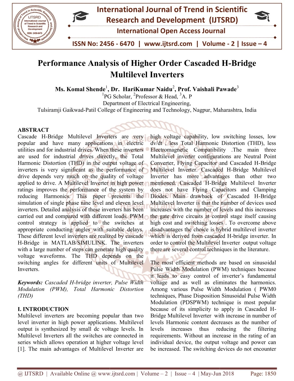
Cascade H Bridge Multilevel Inverters are very popular and have many applications in electric utilities and for industrial drives. When these inverters are used for industrial drives directly, the Total Harmonic Distortion THD in the output voltage of inverters is very significant as the performance of drive depends very much on the quality of voltage applied to drive. A Multilevel Inverter in high power ratings improves the performance of the system by reducing Harmonics. This paper presents the simulation of single phase nine level and eleven level inverters. Detailed analysis of these inverters has been carried out and compared with different loads. PWM control strategy is applied to the switches at appropriate conducting angles with suitable delays. These different level inverters are realized by cascade H Bridge in MATLAB SIMULINK. The inverters with a large number of steps can generate high quality voltage waveforms. The THD depends on the switching angles for different units of Multilevel Inverters. Ms. Komal Shende | Dr. HariKumar Naidu | Prof. Vaishali Pawade "Performance Analysis of Higher Order Cascaded H-Bridge Multilevel Inverters" Published in International Journal of Trend in Scientific Research and Development (ijtsrd), ISSN: 2456-6470, Volume-2 | Issue-4 , June 2018, URL: https://www.ijtsrd.com/papers/ijtsrd14456.pdf Paper URL: http://www.ijtsrd.com/engineering/electrical-engineering/14456/performance-analysis-of-higher-order-cascaded-h-bridge-multilevel-inverters/ms-komal-shende<br>

E N D
International Research Research and Development (IJTSRD) International Open Access Journal International Open Access Journal International Journal of Trend in Scientific Scientific (IJTSRD) ISSN No: 2456 ISSN No: 2456 - 6470 | www.ijtsrd.com | Volume 6470 | www.ijtsrd.com | Volume - 2 | Issue – 4 Performance Analysis of Performance Analysis of Higher Order Cascaded H Multilevel Inverters rder Cascaded H-Bridge Ms. Komal Shende1, Dr. HariKumar Naidu 1PG Department of Tulsiramji Gaikwad-Patil College of Patil College of Engineering and Technology, Nagpur, Maharashtra, India , Dr. HariKumar Naidu2, Prof. Vaishali Pawade PG Scholar, 2Professor & Head, 3A. P Department of Electrical Engineering, Prof. Vaishali Pawade3 , Maharashtra, India high voltage capability, low switching losses, low dv/dt , less Total Harmonic Distortion (THD), less Electromagnetic Compatibility .The main three Multilevel inverter configurations are Neutral Point Converter, Flying Capacitor and Cascaded H Multilevel Inverter. Cascaded H Inverter has more advantages than other two mentioned. Cascaded H-Bridge Multilevel Inverter does not have Flying Capacitors and Clamping Diodes. Main drawback of Cascaded H Multilevel Inverter is that the number of devices used increases with the number of levels and this increases the gate drive circuits at control stage itself causing high cost and switching losses . To overcome above disadvantages the choice is hybrid multilevel inverter which is derived from cascaded H order to control the Multilevel Inverter there are several control techniques in the literature. The most efficient methods are based on sinusoidal Pulse Width Modulation (PWM) techniques because it leads to easy control of inverter’s fundamental voltage and as well as eliminates the harmonics. Among various Pulse Width Modulation ( PWM0 techniques, Phase Disposition Sinusoidal Pulse Width Modulation (PDSPWM) technique is most popular because of its simplicity to apply in Cascaded H Bridge Multilevel Inverter with increase in number of levels Harmonic content decreases as the number of levels increases thus requirements. Without an increase in the rating of an individual device, the output voltage and power can be increased. The switching devices do not encounter ABSTRACT Cascade H-Bridge Multilevel Inverters are very popular and have many applications in electric utilities and for industrial drives. When these inverters are used for industrial drives directly, the Total Harmonic Distortion (THD) in the output voltage of inverters is very significant as the performance of drive depends very much on the quality of vo applied to drive. A Multilevel Inverter in high power ratings improves the performance of the system by reducing Harmonics. This paper presents the simulation of single phase nine level and eleven level inverters. Detailed analysis of these inverters carried out and compared with different loads. PWM control strategy is applied to the switches at appropriate conducting angles with suitable delays. These different level inverters are realized by cascade H-Bridge in MATLAB/SIMULINK. The inverte with a large number of steps can generate high quality voltage waveforms. The THD depends on the switching angles for different units of Multilevel Inverters. Keywords: Cascaded H-bridge inverter, Pulse Width Modulation (PWM), Total Harmonic Distortio (THD) I. INTRODUCTION Multilevel inverters are becoming popular than two level inverter in high power applications. Multilevel output is synthesized by small dc voltage levels. In Multilevel Inverters all the switches are connected in series which allows operation at higher voltage level [1]. The main advantages of Multilevel Inverter are Bridge Multilevel Inverters are very popular and have many applications in electric utilities and for industrial drives. When these inverters are used for industrial drives directly, the Total Harmonic Distortion (THD) in the output voltage of inverters is very significant as the performance of drive depends very much on the quality of voltage applied to drive. A Multilevel Inverter in high power ratings improves the performance of the system by reducing Harmonics. This paper presents the se nine level and eleven level inverters. Detailed analysis of these inverters has been carried out and compared with different loads. PWM control strategy is applied to the switches at appropriate conducting angles with suitable delays. These different level inverters are realized by cascade Bridge in MATLAB/SIMULINK. The inverters with a large number of steps can generate high quality voltage waveforms. The THD depends on the switching angles for different units of Multilevel high voltage capability, low switching losses, low dv/dt , less Total Harmonic Distortion (THD), less Electromagnetic Compatibility .The main three nverter configurations are Neutral Point Converter, Flying Capacitor and Cascaded H-Bridge Multilevel Inverter. Cascaded H-Bridge Multilevel Inverter has more advantages than other two Bridge Multilevel Inverter apacitors and Clamping Diodes. Main drawback of Cascaded H-Bridge Multilevel Inverter is that the number of devices used increases with the number of levels and this increases the gate drive circuits at control stage itself causing losses . To overcome above disadvantages the choice is hybrid multilevel inverter which is derived from cascaded H-bridge inverter. In order to control the Multilevel Inverter output voltage there are several control techniques in the literature. st efficient methods are based on sinusoidal Pulse Width Modulation (PWM) techniques because it leads to easy control of inverter’s fundamental voltage and as well as eliminates the harmonics. Among various Pulse Width Modulation ( PWM0 isposition Sinusoidal Pulse Width Modulation (PDSPWM) technique is most popular because of its simplicity to apply in Cascaded H- Bridge Multilevel Inverter with increase in number of levels Harmonic content decreases as the number of bridge inverter, Pulse Width Modulation (PWM), Total Harmonic Distortion Multilevel inverters are becoming popular than two level inverter in high power applications. Multilevel output is synthesized by small dc voltage levels. In Multilevel Inverters all the switches are connected in allows operation at higher voltage level [1]. The main advantages of Multilevel Inverter are reducing reducing the the filtering filtering requirements. Without an increase in the rating of an individual device, the output voltage and power can be increased. The switching devices do not encounter @ IJTSRD | Available Online @ www.ijtsrd.com @ IJTSRD | Available Online @ www.ijtsrd.com | Volume – 2 | Issue – 4 | May-Jun 2018 Jun 2018 Page: 1850
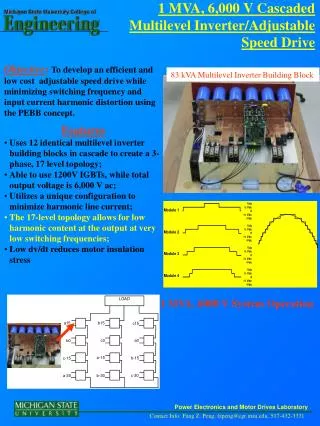
International Journal of Trend in Scientific Research and Development (IJTSRD) ISSN: 2456-6470 any voltage sharing problems. The simulation of single phase nine level, eleven level and thirteen level inverters is done in MATLAB (Simulink). The FFT spectrums for the outputs are compared and presented to validate the proposed control strategy. Vdc with three levels, -2Vdc to +2Vdc with five-level and - 3Vdc to +3Vdc with seven-level inverter. x The number of output phase voltage levels in a cascaded inverter is defined by m=2s+1. .. (1) where, s - is the number of dc sources. The cascade multilevel inverter consists of a number of H-bridge inverter units with separate dc source for each unit and is connected in cascade or series as shown in Fig.1 Each H-bridge can produce three different voltage levels: +Vdc, 0 and –Vdc by connecting the dc source to ac output side by different combinations of the four switches S1, S2, S3, and S4. The ac output of each H-bridge is connected in series such that the synthesized output voltage waveform is the sum of all of the individual H-bridge outputs. By connecting sufficient number of H-bridges in cascade and using proper modulation scheme, a nearly sinusoidal output voltage synthesized. .II. MULTILEVEL INVERTERS The voltage source inverters produce an output voltage or a current with levels either 0,+Vdc , -Vdc. They are known as the two-level inverter. To obtain a quality output voltage or a current waveform with a minimum amount of ripple content, they require high switching frequency along with various pulse width modulation strategies. The Multilevel Inverters have drawn tremendous interest in the power industry. It may produce high-power, high-voltage inverter with the multilevel structure because of the device, which voltage stresses are controlled in the structure. 1.Have less switching device as far as possible. 2.Be capable of withstanding very high input voltage. 3.Have lower switching frequency for each switching devices. Multilevel inverters generate a staircase waveform. By increasing the number of output levels, the output voltages have more steps and harmonic content on the output voltage and the THD values are reduced. Therefore, they produce high quality output voltage by increasing the number of levels. Different topologies available in multilevel inverters are as follows. A.Diode Clamped Multilevel Inverter B.Capacitor Clamped Multilevel Inverter C.Cascaded H-Bridge Multilevel Inverter In Cascaded H-bridge multilevel inverter topology, the H-bridges are cascaded in every phase. With the increase in H-bridges in a phase, the output voltage waveform is tends to be more sinusoidal. In n- level topology, (n-1)/2 identical H-bridges are used in every phase. There must be a separate DC source for the DC bus of every individual H-bridge. The resulting phase voltage is synthesized by the addition of the voltages generated by the different cells. In a 3-level cascaded inverter each single-phase full-bridge inverter generates three voltages at the output: +Vdc, 0, -Vdc (zero, positive dc voltage, and negative dc voltage). This is made possible by connecting the capacitors sequentially to the ac side via the power switches. The resulting output ac voltage swings from -Vdc to + waveform can be IFigure 1 Topology of Cascaded Multilevel Inverter The number of levels in the output phase voltage and line voltage are 2s+1 and 4s+1 respectively, where s is the number of H-bridges used per phase. For example, Three H- Bridges Five H-bridges and Seven H-bridges per phase are required for 7-level, 11-level and 15-level multilevel inverter respectively. The magnitude of the ac output phase voltage is the sum of the voltages produced by H-bridges @ IJTSRD | Available Online @ www.ijtsrd.com | Volume – 2 | Issue – 4 | May-Jun 2018 Page: 1851
International Journal of Trend in Scientific Research and Development (IJTSRD) ISSN: 2456-6470 Table 1. Comparison between Different Level Inverter Topologies Topology Diode Clamped IV .SELECTIVE HARMONIC ELIMINATION Selective Harmonic Elimination Pulse Width Modulation (SHEPWM) technique is one of the control techniques for inverters. It is mainly used for reducing the harmonic content in single phase and three phase inverters and to improve the power quality. The selection of switching angles for eliminating particular harmonic is difficult. The elimination of low-order harmonics is an important issue in power electronics applications. Selective Harmonic Elimination (SHE) is a low switching frequency strategy that uses calculated switching angles to eliminate certain harmonics in the output voltage. With the help of Fourier series analysis the amplitude of any odd harmonic in the output signal can be calculated. The switching angles must however be lower than ?/2 degree and for a number of switching angles a harmonic component can be affected, where number of harmonics can be eliminated. If angles were to be larger than ?/2 correct output signal would not be achievable. Higher harmonics can be filtered out with additional filters added between the inverter and the load if needed. Performance of inverter is improved by incorporating selective harmonic elimination. In this method the switching angles are computed such that a desired fundamental sinusoidal voltage is produced while at the same time certain order harmonics are eliminated. Lower Order Harmonic: The LOH is that harmonic component whose frequency is closest to the fundamental one, and its amplitude is greater than or equal to 3% of the fundamental component. Higher Order Harmonic: The HOH is that harmonic component whose frequency is far away from the fundamental one. Other Order Harmonic: Even order harmonics is a one which is the multiple of two. For example, second-order harmonic is two times the frequency of the fundamental, and a fourth-order harmonic is four times the frequency of the fundamental and so on. Odd order harmonics includes third, fifth, seventh, eleventh and so on. The triple harmonics are those which are the multiples of fundamental one with three. E.g., third, ninth and so on are third order harmonics, which gets cancelled out in three phase applications. S. No Flying Capacitor Cascade d H- Bridge 2(m-1) 1 Power semi conductor Switches Clamping diodes per phase DC bus capacitors Balancing capacitors per phase Voltag unbalanci ng 2(m-1) 2(m-1) 2 (m-1) (m-2) 0 0 3 (m-1) (m-1) (m-1)/2 4 0 (m-1) (m-2)/2 0 5 Average High Very small III. METHODS FOR HARMONIC REDUCTION IN INVERTERS One of the most important aspects of a system is the reduction of harmonics that are present in the system. In case of an inverter, it is very important to remove the harmonics from the ac output. The harmonics present in a dc to ac inverter are very much obvious compared to the harmonics that can be present in an ac to dc converter. This is because of the output of dc to ac inverter being ac. Thus, the filters that are used in dc to ac inverter have different designs compared to the filters used in ac to dc converters. In case of ac to dc converters, the main objective is to improve the output voltage ripple. Thus, passive filters can be easily used in order to improve the output of an ac to dc converter. While, in case of dc to ac inverter, the harmonic reduction is harder and it also includes the use of active filters. As the output of dc to ac inverters is alternating, it is very important to produce sinusoidal output waveforms. The filters used to remove the harmonics from the inverters are more complex and consists of large number of inductors and capacitors to remove the harmonics of higher order. Thus, in order to avoid the cost of such expensive and complex filters controlling the width or reducing the number of pulses may result into reduction of harmonics. One such technique is explained below. @ IJTSRD | Available Online @ www.ijtsrd.com | Volume – 2 | Issue – 4 | May-Jun 2018 Page: 1852
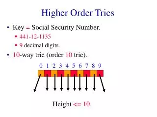
International Journal of Trend in Scientific Research and Development (IJTSRD) ISSN: 2456-6470 these harmonic equations. In Newton–Raphson (N–R) method is also used to solve the nonlinear equations the disadvantage of iterative methods is their dependence on an initial guess and divergence problems are likely to occur for large numbers of inverter levels. Also, they can only find one set of solutions. In Gauss–Newton method it is complicated and time-consuming and requires new expression when voltage level or input dc voltage is changed. This method does not suggest any optimum solution; the second group of methods has been applied based on evolutionary algorithms. These methods are simple and can be used for problems with any number of levels. They are free from derivation. The algorithm is also used to solve these equations; Genetic Algorithm is widely used and is simpler and more applicable. But the probability of reaching to a global solution and the effect of running times is very slow. Sinusoidal PWM Sinusoidal Pulse Width Modulation is one of the most popular modulation techniques among the others applied in power switching devices. In case of sinusoidal pulse width modulation, all the pulses are modulated individually. A sinusoidal reference voltage waveform is compared with a triangular carrier waveform to generate gate signals for the switches of inverter. The fundamental frequency SPWM control method was proposed to minimize the switching losses. It has more total harmonic distortion Figure 2 Output phase voltage waveform for 7- level CMLI V. EXISTING METHOD The Newton-Raphson (N-R) method is one of the fastest iterative methods. This method begins with an initial approximation and generally converges at a zero of a given system of nonlinear equations. The N- R method is to be implemented to compute the switching angles for the system given by (4-9). The Switching angles which are in the range of 0 to π/2 producing desired fundamental voltage along with elimination of 5th ,7th, 11th,and 13th harmonic components for a given modulation index are feasible solutions. The N-R method implemented was based on trial and error method for estimation of initial guess and for which solutions exist. Once a solution set was obtained, successive solutions were computed by using previous solution set as initial guess for the next one; proceeding in this way, only one solution set was obtained. Here, the N-R method is implemented in a different way for which an arbitrary initial guess between 0 to π/2 is assumed and switching angles (keeping all switching angles in the feasible range) along with the error (% content of 5th, 7th, 11th and 13th harmonic components) are computed for complete range of by incrementing its value in small steps (say 0.0001). The different solution sets are obtained for a particular range of where they exist i.e. the error is zero for feasible solutions; after getting preliminary solution sets, complete solution sets are computed by using known solutions as initial guess. VI.PROPOSED WORK In Conventional methods equal conducting angles are chosen for multilevel inverters. In this method harmonics were found in output voltage of multilevel inverter. Then the method involves solving for harmonic equations using theory of resultants. Since the output waveform of multilevel inverter follows Fourier series different methods makes use of Fourier series for generating desired sinusoidal waveform through numerical equations. Software packages such as Mathematical and Math-cad is used for solving Figure 3. Sinusoidal PWM @ IJTSRD | Available Online @ www.ijtsrd.com | Volume – 2 | Issue – 4 | May-Jun 2018 Page: 1853
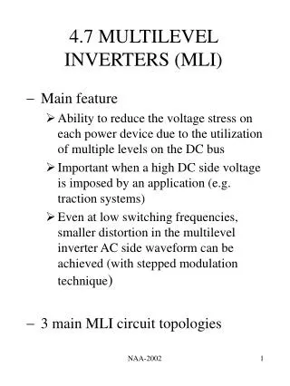
International Journal of Trend in Scientific Research and Development (IJTSRD) ISSN: 2456-6470 Several multicarrier techniques have been developed to reduce the distortion in multilevel inverters, based on the classical SPWM with triangular carriers. Some methods use carrier disposition and others use phase shifting of multiple carrier signals. A number of – cascaded cells in one phase with their carriers shifted by an angle and using the same control voltage produce a load voltage with the smallest distortion. The effect of this carrier phase-shifting technique can be clearly observed this result has been obtained for the multi cell inverter in a seven-level configuration, which uses three series-connected cells in each phase. The smallest distortion is obtained when the carriers are shifted by an angle of. A very common practice in industrial applications for the multilevel inverter is the injection of a third harmonic in each cell. Another advantageous feature of multilevel SPWM is that the effective switching frequency of the load voltage is times the switching frequency of each cell, as determined by its carrier signal. This property allows a reduction in the switching frequency of each cell, thus reducing the switching losses. BLOCK DIAGRAM wave is compared with sinusoidal modulating wave. Fig 6 shows the output voltage for 9 level CMLI. Figure 7, 8, & 9 shows the different THD analysis for R,RL,RLC. Figure 5 Simulink Diagram for 9 level CMLI Figure 6. Output Waveform for 9 Level FFT Analysis Figure 7 FFT Analysis for R-load Figure 4 Block Diagram for Proposed Method VII . RESULTS AND DISCUSSIONS Load harmonics can cause the over heating of the motor. on the other hand source harmonics are generated by power supply. The multilevel inverter was introduced to increase the converter output voltage as the number of level are increase the synthesis output waveform has more steps which produce stair case wave that approach the desire waveform. Hence a proposed model simulated different various levels of inverter with different loads and compare to other level. Cascaded Multilevel Inverter (9Level) A single phase PWM inverter consists of a PWM generator, cascaded H-bridge with dc source shown in figure 5. In this PWM generator triangular carrier Figure 8 .FFT Analaysis for RL--Load Figure 9 FFT Analysis for RLC--Load @ IJTSRD | Available Online @ www.ijtsrd.com | Volume – 2 | Issue – 4 | May-Jun 2018 Page: 1854
International Journal of Trend in Scientific Research and Development (IJTSRD) ISSN: 2456-6470 Cascaded Multilevel Inverter for 11 Level In similar way as discussed in case of eleven -level CMLI, The harmonic components of 5th, 7th, 11th and 13th orders are eliminated. Figure 12 shows the output voltage for 9 levels CMLI. Figure 13, 14 & 15 shows the different THD analysis for R, RL & RLC Figure 14. FFT Analysis for RLC--Load Table 2 Comparison of different Multilevel Inverters Levels/Load R-Load RL-Load RLC- Load 14.48 12.80 9 Level 11 Level 14.49 12.82 14.58 12.95 Figure 10. Simulink Diagram for 11 level CMLI VIII. CONCLUSION This paper has discussed about the Selective Harmonic Elimination. The SHE method has been proposed and developed to reduce specific harmonics for multilevel inverters. Here, the odd numbers of switching angles are selected for reducing the lower order harmonics. The simulation result confirms that the lower order harmonics and THD has been effectively reduced to 10%. In this work, the lower order harmonics have been reduced by using the SHE method and by making use of the BEE Algorithm the switching angles are optimized to improve the output voltage quality but still it’s found that the third order harmonics is with nominal magnitude of about 2 and the fifth and seventh order harmonics are further reduced by tuning the BEE algorithm. Therefore it’s aimed to eliminate the LOH fully in future work. REFERENCES 1.Ashok. B, Rajendran. A “Selective Harmonic Elimination of Multilevel SHEPWM Technique ” International Journal of Soft Computing and Engineering (IJSCE) ISSN: 2231- 2307, Volume-3, Issue-2, May 2013. Figure 11. Output Waveform for 11 Level FFT Analysis for 11 Level Inverter Inverter Using Figure 12.FFT Analysis for R—Load 2.Ayoub Kavousi, Behrooz Vahidi, Reza Salehi, Mohammad Kazem Farokhnia, and S. Hamid Fathi “Application of the Bee Algorithm for Elimination Strategy in Multilevel Inverters” IEEE transactions on power electronics,Volume- 27,No.4,April 2012. Bakhshizadeh, Naeem Selective Harmonic 3.Du. Z, Tolbert. L. M, and Chiasson. J. N, “Active harmonic elimination for multilevel converters,” Figure 13. FFT Analysis for RL--Load @ IJTSRD | Available Online @ www.ijtsrd.com | Volume – 2 | Issue – 4 | May-Jun 2018 Page: 1855
International Journal of Trend in Scientific Research and Development (IJTSRD) ISSN: 2456 al Journal of Trend in Scientific Research and Development (IJTSRD) ISSN: 2456 al Journal of Trend in Scientific Research and Development (IJTSRD) ISSN: 2456-6470 IEEE Trans. Power Electron., vol. 21, 459–469, Mar. 2006. IEEE Trans. Power Electron., vol. 21, no. 2, pp. voltage THD in multilevel inverter with unequal DC sources,” IEEE Trans. Ind. Electron., vol. 58, voltage THD in multilevel inverter with DC sources,” IEEE Trans. Ind. Electron., vol. 58, no. 8, pp. 3359–3372, Aug. 2011. 3372, Aug. 2011. 4.Dahidah. M. S. A, and Agelidis. V. harmonic elimination PWM control for cascaded multilevel voltage generalized formula,” Electron., vol. 23, no. 4, pp. 1620–1630, Jul. 200 V. G, “Selective 8.Hagh. M. T, Taghizadeh. “Harmonic minimization in multilevel inverters using modified species- optimization,” IEEE Trans. Power 24, no. 10, pp. 2259–2267,Oct. 2009. 2267,Oct. 2009. harmonic elimination PWM control for cascaded multilevel voltage source generalized formula,” T, Taghizadeh. H, and Razi. K, “Harmonic minimization in multilevel inverters source IEEE IEEE converters: Trans. Trans. 1630, Jul. 2008. converters: A A Power Power -based particle swarm optimization,” IEEE Trans. Power Electron., vol. 5.Fei.W, Ruan. X, and Wu. B, “A generalized formulation of quarter wave symmetry SHE PWM problems for multilevel inverters,” IEEE Trans. Power Electron., vol. 24, no. 7, pp. 1758 1766, Jul. 2009. B, “A generalized wave symmetry SHE- 9.Hagiwara. M, Nishimura. medium-voltage motor drive with a modular multilevel PWM inverter,” IEEE Trans. Power Electron., vol. 25, no. 7, pp. 1786 Electron., vol. 25, no. 7, pp. 1786–1799, Jul. 2010. M, Nishimura. K, and Akagi. H, “A voltage motor drive with a modular multilevel PWM inverter,” IEEE Trans. Power PWM problems for multilevel inverters,” IEEE Trans. Power Electron., vol. 24, no. 7, pp. 1758– 6.Flourentzou. Demetriades. G. D, “VSC-based HVDC power transmission systems: An overview,” IEEE Trans. Power Electron., vol. 24, no. 3, pp. 592 2009. 10.Hatti. N, Hasegawa. K, and Akagi. transformer less motor drive using a five diode-clamped PWM inverter for energy savings of pumps and blowers,” IEEE Trans. Power Electron., vol. 24, no. 3, pp. 796 , no. 3, pp. 796–803, Mar. 2009. N, Agelidis. V. G. , and K, and Akagi. H, “A 6.6-kV less motor drive using a five-level clamped PWM inverter for energy savings of pumps and blowers,” IEEE Trans. Power based HVDC power transmission systems: An overview,” IEEE Trans. Power Electron., vol. 24, no. 3, pp. 592–602, Mar. 7.Farokhnia. N, Vadizadeh. H, Fathi. Anvariasl. F, “Calculating the formula of line Fathi. S. H, and the formula of line @ IJTSRD | Available Online @ www.ijtsrd.com Available Online @ www.ijtsrd.com | Volume – 2 | Issue – 4 | May-Jun 2018 Jun 2018 Page: 1856