Download
1 / 23
230 likes | 365 Vues
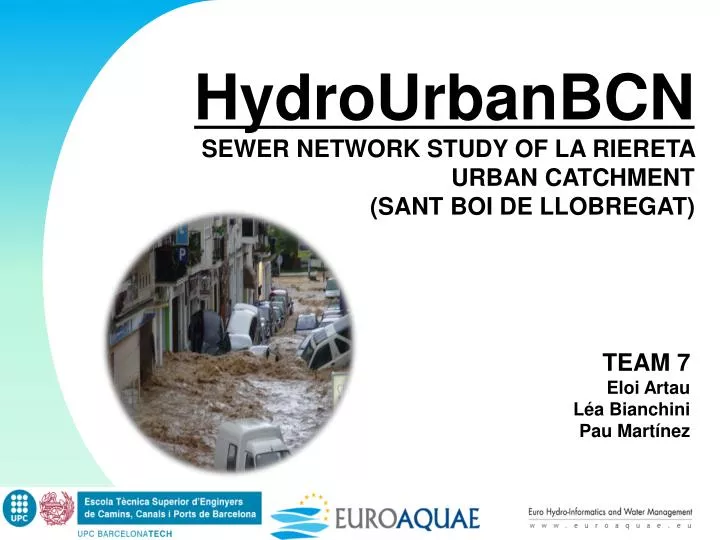
HydroUrbanBCN SEWER NETWORK STUDY OF LA RIERETA URBAN CATCHMENT (SANT BOI DE LLOBREGAT). TEAM 7 Eloi Artau Léa Bianchini Pau Martínez. Index. Localization Objective Methodology Modeling of the network Effective Rainfall Continuous simulation

E N D
HydroUrbanBCN SEWER NETWORK STUDY OF LA RIERETA URBAN CATCHMENT (SANT BOI DE LLOBREGAT) TEAM 7 Eloi Artau Léa Bianchini Pau Martínez
Index • Localization • Objective • Methodology • Modeling of the network • Effective Rainfall • Continuous simulation • Analysis of the sewer network rehabilitation • Conclusions
Localization • “La Riereta” is a neigborhoodof SantBoi de Llobregat. • SantBoi de Llobregat is a small town of 83.000 inhabitants near to Barcelona. • The town, covers an area of approximately 21.48 km². • The case of study area is 17 ha, with high levels of impervious surfaces and medium slope values. • “La Riereta” area have unitary sewer system.
Objective • First task: Catchment definition and discretization. • Second task: Modellisation of the catchment. • Determination of the terrain imperiousness and/or constant losses. • Determination of the Manning’s roughness coefficients for the entire sewer network as well as for the whole catchment. • Calibration and Validation of the hydrological model. • Third task: Determination of the effective rainfall to be used for the simulation. • Fourth task: Continuous simulations. • Conclusions: Changes or/and modifications on either the sewer network or urban catchment so that hydraulic condition criterion could be met Specifictask of team 7
Methodology • Catchmentdefinitionanddiscretization: • Total area of aprox. 17 Ha. Outletnode #9 Manhole #61 16,67 Ha.
Methodology • Definition of thesub-catchments: • Main pipes • Outlet of eachsub-catchment (junctions) • Longestflowpath • Slope of eachsub-basin • Average of different slopes • Roof slope (1,5%) • 16 Sub-catchments of aprox. 1 Ha. Sub-catchment #3
Methodology Modelednetworkwith SWMM 5.0
Modeling of the network Measured Data La Riereta Project Comparation SWMM Model Results Discretization Basin Estimated Data Analysis Calibration process • Calibration paremeters: • Imperviousness of the terrain (%). • Constant losses (mm/h). • Characteristic width of each sub-catchment (m). • Manning’s coefficient for surface of the catchment. • Manning’s coefficient for the pipe.
Modeling of the network Calibrationparameters • Calibration paremeters: • Imperviousness of the terrain (%). • Constant losses (mm/h). • Characteristic width of each sub-catchment (m). • Manning’s coefficient for surface of the catchment. • Manning’s coefficient for the pipe.
Modeling of the network Calibration The final adopted values are:
Modeling of the network • Validation • Once the model is calibrated, is time to validate it. The rainfall used in this case is Santa Cecilia. • The model will be considered well calibrated 11
Effective Rainfall • Once the model is calibrated, it is ready to start simulating rainfalls. • Use the equations ,that show below, for can built the IDF curve and use 10 years of return period. These belong to the region of Barcelona–Fabra. Design Storm (Alternative Blocks) 12
Continuous simulation • Resultsanalysis: • Keypoints: Outlet outflow • Node flooding • Pipe capacity Time of study Outletoutflow (node#9)
Continuous simulation a • Model results: Model sequence Areadelimitation Area 2 Area 1
Continuous simulation a • Study of thedefinedAreas: Model sequence Areadelimitation Area 2 Area 1 Area 2 Area 1 • J47: • All Runofffrom • Sub-catchments 9&10 • Ø 300mm • J48: • Juncition for all uppersub-catchments
Continuous simulation a • Numericalresults: Model sequence Areadelimitation Area 1 Area 2 Conduit surcharging Node flooding AverageLimitedCapacity of 3 min. AveragetimeFlooded of 3 min. Littlevolume of waterregardingthesurface of thestreet
Analysis of the sewer network rehabilitation a • Considerations: • No changes can be done to the network planlayout. • Rehabilitation of the network bychangingcross-sections, materials, slopes, etc. Considerations • Other: • Economic cost of theproposedchanges • Duration of thechanges • Inconveniencecaused to thepopulation • Safety of thesolution
Analysis of the sewer network rehabilitation a • Firstproposal: • Cleaningthe network andrehabilitation of the pipes. Considerations Firstproposal • Cleaningthe network: • Most economicalsolution. • Manningchange 0.022 0.020 (Pipes cleanbutstilldamaged) • Flooding. • Cleaning + painting: • Paintingwithapporopiateproductsthe interior of the pipes • Manningchange 0.020 0.016 (Lessfrictionbutstilldamaged) • Flooding. • Bothsolutionsrequire constant maintenace !!!
Analysis of the sewer network rehabilitation a • Secondproposal: • Major works, change of pipes. Considerations • Changing the material but not the cross-section dimensions: • CorrugatedPolyethilene pipes Smootherwalls • Floodingcould be prevented • Highriskif pipes notcleanedfrequently (Manningvariation) Firstproposal Secondproposal Material Cross-section • Changing the cross-section geometry but not its area: • Variable cross-sectiongeometry • Smallarea • Betterefficiency in dryperiods • Higher cost
Analysis of the sewer network rehabilitation a • Secondproposal: • Major works, change of pipes. Considerations • Increasing or changing the slopes of the conduits: • No reverseflowappears, correctdirection of the slopes • Usefull in flat areas Enoughvelocity? • Higheconomical cost whenchanging slopes Firstproposal Secondproposal Material Cross-section Slope • Changing the cross-section area using concrete prefabricated circular pipes: • All pipes prefabricated • Circular cross-section • Concrete Manning coeff. 0,015 (new pipes) & 0,02 (old) • Requires major works Identify critical points Area Final solution
Analysis of the sewer network rehabilitation • Final solution: • Step 1: • Pipe 5: Circular 300mm Circular 400mm • Pipe 12: Circular 300mm Circular 400mm Considerations Firstproposal Secondproposal • Step 2: • Pipe 7: Circular 400mm Circular 500mm • Pipe 8: Circular 400mm Circular 500mm • Pipe10: Circular 600mm Circular 800mm • Pipe11: Rect. 300x400mm Circular 500mm Material Cross-section Slope Area • Step 3: • Pipe 3: Circular 1100mm Circular 1200mm • Pipe 4: Circular 1000mm Circular 1200mm Fromcleaned pipes
Conclusions • Changes: • All flooding is prevented! • Other considerations accepting some flooding: • Riskcriteria Geometry of thestreets • Less major works Lessincovinience to thepopulation & Less cost $ • Safety • Maybe non acceptedbythepopulation (non visual solution)
HydroUrbanBCN Thank you for you attention! TEAM 7 Eloi Artau Léa Bianchini Pau Martínez