Download
1 / 13
130 likes | 249 Vues
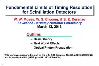
AV Timing Limits. BridgeCo AG Georg Dickmann georg.dickmann@bridgeco.net. Outline. Jitter / latency limits imposed by audio applications The audio clock path Identification and analysis of sources of timing inaccuracy A simple 1394 cycle based timing offset prediction scheme Conclusion.

E N D
AV Timing Limits BridgeCo AG Georg Dickmann georg.dickmann@bridgeco.net Georg Dickmann, BridgeCo AG.
Outline Jitter / latency limits imposed by audio applications The audio clock path Identification and analysis of sources of timing inaccuracy A simple 1394 cycle based timing offset prediction scheme Conclusion Georg Dickmann, BridgeCo AG.
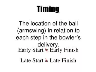
Limits imposed by digital audio (1) High frequency jitter components are audible as modulation products. Modulation products may be masked by nearby signal tones or the absolute hearing threshold (see next slide). Low frequency jitter components become audible in a multi-channel environment. Localization of signal relies on • Interaural Intensity Difference (unaffected by jitter) (fsignal > 1000 Hz, 1..12 dB for left/right panning) • Interaural Time Difference (caused by unequal delay / jitter) (fsignal < 1600 Hz, 3 μs < Dt < 630 μs: smearing, Δt > 630 μs: precedence effect) Georg Dickmann, BridgeCo AG.
Limits imposed by digital audio (2) The left figure gives the maximum tolerable sinusoidal jitter amplitude over frequency. The right figure illustrates the spectral broadening of sine signals due to jitter as given by the green curve on the left. Georg Dickmann, BridgeCo AG.
The audio clock path Audio source with Frequency fs Transmitter inserts Timestamp = Local Time + ΔT Receiver presents data when (Timestamp == Local Time) PLL for recovery of fs Georg Dickmann, BridgeCo AG.
Sources of Timing Inaccuracy • Time is distributed at regular intervals T by a (wireless) cycle master. • Receivers update their local time with the received time. • In-between updates, local time is based on a fixed local oscillator. A remaining phase offset may be attributed to three independent sources: • Constant phase offset due to processing and signal propagation. • Variable phase offset due to uncertainty at transmission over (wireless) channel • Phase offset ramp due to a frequency offset of the local oscillator Georg Dickmann, BridgeCo AG.
Constant phase offset If it can be made known to the receiver of a timing message (beacon or cycle start packet) it can be easily compensated • Could be a property of a node reported in a register. • Could be made measurable by a ping-like operation. • A known value could be compensated by both transmitter and receiver of a timing message. Georg Dickmann, BridgeCo AG.
Update Uncertainty Characteristics: • Randomly distributed within [-u/2 u/2] • Worst case jitter amplitude is u. • Main frequency components are below 2/T with T: update interval • A part of the jitter energy will disappear after PLL recovery if f3dB,PLL « 2/T Georg Dickmann, BridgeCo AG.
Update Uncertainty (Example) Let update uncertainty be equally distributed within [-200ns 200ns]. Let T = 2 ms. Let a 2nd order PLL recover the sampling frequency. A sample run during 30 sec results in a maximum jitter amplitude of 350 ns for a 50 Hz PLL cutoff 170 ns for a 10 Hz PLL cutoff Georg Dickmann, BridgeCo AG.
Delay ramp-up between updates Characteristics: • Stationary sawtooth jitter j(t) with amplitude u T · Δf • Fourier decomposition leads to a constant + harmonic components: Conclusion: • Assuming Δfmax = 200 ppm, T = 2 ms then u = 400 ns. An harmonic jitter component at 500 Hz with amplitude 2x400ns/pi = 255 ns is produced. Assuming a jitter limit of 1 ns at 500 Hz, a subsequent PLL needs an attenuation of 48 dB (3dB cutoff at 30 Hz for a 2nd order PLL). • Update intervals > 2 ms are likely to produce unacceptable jitter contributions. • A simple timing offset prediction scheme could greatly reduce constraints on update intervals and frequency offset. Georg Dickmann, BridgeCo AG.
A simple 1394 cycle based timing offset prediction scheme Let N be the number of 1394 cycles between cycle time updates. Let Δu(n) be the clock phase correction at update n. Δc(n) is the required phase correction per 1394 cycle. At each 1394 cycle adjust the cycle time by the correction value Δc(n). (if required skip an appropriate number of adjustments until the cumulated correction values amount a full clock tick of 40 ns) Update the correction value according to Δc(n+1) = Δc(n) + a·Δu(n)/N, 0 < a < 1 Choose a « 1. Georg Dickmann, BridgeCo AG.
Evaluation of Predictor Performance • Simulation with parameters: N = 16 (T = 2 ms), a = 1/64 • Update uncertainty is 400 ns Δf = 200 ppm Δf = 10 ppm Georg Dickmann, BridgeCo AG.
Conclusion / Proposal Keep total timing error per link below 1/3 of thresholds to accomodate for several communication hops. Make phase offset independent from constant delay due to transmitter/receiver processing and queuing of timing update information. Timer update interval length may be freely chosen if frequency offset prediction is used (provided that packet transfer latency is independent from timer update interval length). Keep timer update uncertainty below 0.5 μs. Georg Dickmann, BridgeCo AG.