Download
1 / 8
80 likes | 231 Vues
Systems Analysis & Design Methods. Traditional Techniques: Data Flow Diagrams (see also handouts !). Structured Analysis & Data Flow Diagrams (DFD). 70ies and 80ies Gane and Sarson, DeMarco/Yourdon Process-centered

E N D
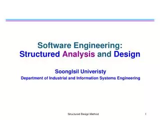
Systems Analysis & Design Methods Traditional Techniques: Data Flow Diagrams (see also handouts !)
Structured Analysis &Data Flow Diagrams (DFD) • 70ies and 80ies • Gane and Sarson, DeMarco/Yourdon • Process-centered • Analysts draw a series of process models called ‘data flow diagrams’ along with their inputs, outputs and files. • The models show the flow of data together with places where data is stored. Older techniques
DFD shapes Process: needs both input and output External agent: output must go to process, input must come from process File/database/datastore: output must go to process, input must come from process Older techniques
A simple DFD (part) Older techniques
Event driven Process Modelling(see handouts) • (1) Context DFD: 1 proces ‘The System’ + many external agents ‘The System’ is exploded to form the decomposition diagram • (2) Decomposition Diagram: tree of processes • ‘The System’-proces is divided into functions • Functions are devided into events (4) Each event gives rise to its own small DF diagram called event diagram • (5) Event diagrams (DFD) Event diagrams are combined to form the system diagram • (6) System diagram Each event process that requiress additional detail has its own primitive diagram: • (7) Primitive diagrams (DFD) Note: The events are described in event lists. For each event this list gives the corresponding actor and response to the event. Note: The data passed to and from the processes can serve as a starting point for the data model in Entity-Relationship-modeling. Or you can do the data modeling first. Older techniques
Event list example Older techniques
Data & Process model synchronisation:Data to process CRUD-matrix • DFD’s are about process modeling (70ies) • ER-diagrams are about data modeling (80ies). (For now, you can view an ER-model as a high level database model.) For every datastore in the process model, there should be exactly one entity (table) in the data model and vice versa. Furthermore, each entity should be created, read, updated and deleted by at least one process (not necessarily the same). For this, you can use a so-called CRUD matrix (see handouts). Older techniques
DFDs: an assessment We read: • Whitten, …[2004] ‘Object-oriented analysis will eventually replace structured analysis’. (p 225) Conclusion: DFD’s may be interesting for the following purposes: • to understand older system documents • maybe to aid business process reengeneering, even if they are not automated • definitely to model data-flows between systems (imports, exports) Note: In general, when doing procedural programming, high level procedural code is often more readable than their corresponding diagrams: flow charts, sequence diagrams, acitivity diagrams. Older techniques