Download
1 / 27
580 likes | 1.18k Vues
Efficiency of Solar Cells. Robert Riestenberg and Aayush Singh Physics 141A April 23, 2013. http://solarcellstringer.com. Outline. Basic Physics of Solar Cells Intrinsic and Extrinsic Semiconductors p-n Junctions Photogeneration and Separation of Charge Carriers

E N D
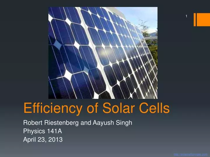
Efficiency of Solar Cells Robert Riestenberg and Aayush Singh Physics 141A April 23, 2013 http://solarcellstringer.com
Outline • Basic Physics of Solar Cells • Intrinsic and Extrinsic Semiconductors • p-n Junctions • Photogeneration and Separation of Charge Carriers • Efficiency of Solar Cells • Shockley-Queisser Limit Derivation • Exceeding the Shockley-Queisser Limit • Multi-Junction Solar Cells • Concentration of Sunlight • Multiple Exciton Generation
Intrinsic Semiconductors • The Fermi Level, EF, corresponds to a potential energy, ε, that is equal to the chemical potential μ at a given temperature. • For intrinsic semiconductors, EF lies in the middle of a small band gap. • In an intrinsic semiconductor, the numbers of electrons and holes can be assumed to be equal. • Intrinsic semiconductors are usually composed of elements with an average valence shell of 4 electrons. (J.W. Morris)
Extrinsic Semiconductors: n-type • N-type extrinsic semiconductors are doped with small amounts of an element that acts as an electron donor. • The additional electrons from the dopant reside in “donor levels” just below the conduction band, leading to a Fermi level that is closer to the conduction band. • Electrons can be excited from the donor levels to produce charge carriers in the conduction band. (J.W. Morris)
Extrinsic Semiconductors: p-type • P-type semiconductors are doped with a small amount of an element that acts as an electron acceptor. • The lack of electrons creates “acceptor levels” just above the valence band, leading to a Fermi level that is closer to the valence band. • Electrons can be excited from the valence band to the acceptor levels to produce free hole charge carriers in the valence band. (J.W. Morris)
p-n Junctions • p-n junctions are created from the contact of p-type and n-type semiconductors. • Prior to contact, EF is higher on the n side. • Upon contact, electrons flow from the n side to the p side, until EF is constant across the interface. • An electric potential (ΔV) develops across the interface, and raises the energy on the p side as higher energy orbitals are filled (ΔE = -eΔV). (J.W. Morris)
Photogeneration of Charge Carriers • Photons contacting the semiconductor can either: • Pass through the material (low energy photons). • Be absorbed by the semiconductor and excite an electron to a higher energy state (high energy photons). • Be reflected off the surface. • The minimum photon energy required to create an exciton (electron-hole pair) is the band gap energy of the material. (Wikipedia)
Photogeneration of Charge Carriers • Much of the solar radiation reaching Earth consists of photons with energies much greater than the band gaps of typical semiconductors. • When higher energy photons are absorbed, electrons are excited further into the conduction band. • But the difference in energy between these photons and the band gap is quickly converted into heat via phonons (lattice vibrations). (Wikipedia)
Charge Carrier Separation • Charges move in two ways: • Drift, driven by the electric field. • Diffusion, driven by concentration gradients. • In thin film solar cells, the electric field penetrates the whole material, so drift is the dominant mode of charge separation. • Excited electrons irreversibly move toward the n side and holes move toward the p side. (Wikipedia) (J.W. Morris)
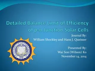
Efficiency of Solar Cells • In 1961 William Shockley and Hans Queisser calculated the maximum theoretical efficiency of an ideal single p-n junction. • The total efficiency is defined as follows: where u(xg) accounts for energy gap losses, v(xg,xc,f) denotes the ratio of the operational voltage to the energy gap, m(xg,xc,f) is the impedance matching factor, and ts is the probability that an electron-hole pair will be produced from a photon. (Wikipedia) /www.ulm.de/sixcms/media.php
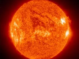
Ultimate Efficiency Derivation: Assumptions • The solar frequency spectrum can be approximated as a black body emitter at 5800 K. • No photons with energy less than the band gap energy are absorbed. • All photons with energy greater than the band gap energy are absorbed. • The useful electrical energy generated from each absorbed photon is equal to the band gap energy. • The system consists of a spherical p-n junction (with Tc= 0 K) surrounded by a spherical black body emitter (with Ts= 5800 K). (Wikipedia) (Liao, Hsu)
Parameters and Definitions (Liao, Hsu)
Ultimate Efficiency Derivation • Photons obey Bose-Einstein statistics, so QS (the number of quanta of frequency greater than νg) can be calculated based on the Planck distribution. • The three-dimensional density of states is proportional to K2 (lecture) and the photon dispersion relation (just as for phonons) is as follows: • Therefore, the density of states (dN/dν) is proportional to ν2/c2.
Ultimate Efficiency Derivation (Liao, Hsu)
(Liao, Hsu) The maximum theoretical Efficiency is 43.96%, for Eg = 1.08 eV
More Realistic Situation:Detailed Balance Principle • Consider a more realistic planar solar cell with a nonzero TC and a view factor relating the incident power to the power of the sun. • The TC = 0 assumption previously allowed radiative recombination to be neglected (negligible population of excited states). • But by the Detailed Balance Principle for a system with a finite excited state population, some electron-hole pairs must recombine and re-radiate photons. • Therefore, the free energy available for electrical work is smaller than the band gap of the material. (Liao, Hsu)
Alternative Explanation… • Consider a gas of N photons with energy E1 and entropy S1. • Upon absorption of a photon by a material, the gas now contains N-1 photons, with energy E2 and entropy S2, where E2 < E1 (energy decreases by E1 – E2) and S2 < S1 (entropy decreases by S1 – S2) • The available free energy for electrical work, ΔF, is given by : ΔF = (E1 – E2) – T(S1 – S2) < (E1 – E2) • Therefore, not all of the absorption energy can be utilized by the solar cell.
Inclusion of Recombination Losses TC = 300K (Liao, Hsu)
Inclusion of Impedance Matching Factor • In a practical device the maximum values of current and voltage (Ish and Vop) cannot be achieved simultaneously, which leads to further losses… • Shockley-Queisser Limit: For a p-n junction with a band gap of 1.34 eV, the maximum efficiency is approximately 33.7% (Wikipedia)
Exceeding the Shockley-Queisser Limit: Multi-Junction Solar Cells A multi-junction solar cell can be made (at higher cost…) by layering different materials on top of each other, with the largest band gap materials on top and decreasing band gap materials through the body of the cell. (Wikipedia)
Exceeding the Shockley-Queisser Limit: Concentration of Sunlight • Another way to increase theoretical efficiency is to concentrate the sunlight using lenses or mirrors. • Provided that the temperature of the cell does not increase, the increase in intensity of light improves the Shockley-Queisser efficiency, since a gas with more photons suffers a smaller change in entropy upon the creation of an exciton. This Amonix system contains thousands of small lenses, each of which focuses sunlight by a factor of 500 onto a small multi-junction cell. (Wikipedia)
Exceeding the Shockley-Queisser Limit: Multiple Exciton Generation (MEG) • Nanocrystal-based solar cell efficiency can be theoretically improved by the generation of multiple electron-hole pairs from the absorption of one photon. • MEG been demonstrated in nanocrystals (quantum dots) such as PbS, PbSe, PbTe, CdS, CdSe, and InAs, as well as in single-walled carbon nanotubes. • The origin of MEG is complicated and still under debate, but one explanation is that light excites a high energy exciton which then decays irreversibly into a quasi-continuum of states available at that energy. http://www.chem.rochester.edu
Conclusion • Solar cells are created by forming an electrical circuit with a p-n junction and a load. • The theoretical efficiency of solar cells is highly limited, even in the limit of perfect engineering. • Researchers are developing ways to increase this maximum efficiency, but the cost of implementing these new technologies remains an issue. • Questions?
References • Shockley, W., Queisser, H.J., Journal of Applied Physics, 32, 510 (1961). • Morris, J. W. The Structure and Properties, Vols. 1-2. McGraw-Hill (2012). • Morris, J. W. Engineering 45 Lecture Slides (2013). • Liao, Bolin and Hsu, Wei-Chun, “An Investigation of Shockley-Queisser Limit of Single p-n Junction Solar Cells”, Massachusetts Institute of Technology 2.997 Project Report (2012).
References (Images) • Slide 1: http://solarcellstringer.com/images/solar_cells_panels_array_monocrystaline.jpg • Slides 3-6, 9: Morris, J. W. Engineering 45 Lecture Slides (2013). • Slides 7-9: http://upload.wikimedia.org/wikipedia/commons/8/86/BandDiagramSolarCell-en.gif • Slide 10: http://www.pres.org.pk/category/re-technologies/solar-energy/solar-pv/ • Slide 11: http://en.wikipedia.org/wiki/File:William_Shockley,_Stanford_University.jpg • Slide 11: http://www.ulm.de/sixcms/media.php/123/thumbnails/Prof_Queisser.jpg.57479.jpg • Slide 12: http://upload.wikimedia.org/wikipedia/commons/1/19/Black_body.svg • Slides 12, 13, 15-17, 19: Liao, Bolin and Hsu, Wei-Chun, “An Investigation of Shockley-Queisser Limit of Single p-n Junction Solar Cells”, Massachusetts Institute of Technology 2.997 Project Report (2012). • Slide 20: http://upload.wikimedia.org/wikipedia/commons/9/99/ShockleyQueisserBreakdown2.svg • Slide 21: http://upload.wikimedia.org/wikipedia/commons/thumb/1/19/StructureMJetspectre.png/550px-StructureMJetspectre.png • Slide 22: http://en.wikipedia.org/wiki/File:Amonix7700.jpg • Slide 23: http://www.chem.rochester.edu/highlights/sum09.php • Slide 24: http://www.nrel.gov/ncpv/images/efficiency_chart.jpg