Download
1 / 13
130 likes | 248 Vues
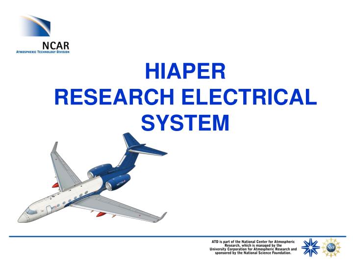
HIAPER RESEARCH ELECTRICAL SYSTEM. HIAPER Research Electrical Systems. Research Power System 115 VAC 400 Hz single phase 115 VAC 60 Hz single phase 115/208 VAC 400 Hz 3 phase 28 VDC Weight on Wheels (WOW) wings only 10 Secondary power distribution locations. 8 Main Cabin 1 Nose area

E N D
HIAPER Research Electrical Systems • Research Power System • 115 VAC 400 Hz single phase • 115 VAC 60 Hz single phase • 115/208 VAC 400 Hz 3 phase • 28 VDC Weight on Wheels (WOW) wings only • 10 Secondary power distribution locations. • 8 Main Cabin • 1 Nose area • 1 Baggage
HIAPER Research Electrical Systems-Wing • Six Wing Hard Point locations • 115 VAC 60 Hz single phase (2-circuits) • 115 VAC 400 Hz single phase • 28 VDC WOW • Signal • 8 analog • 4-channel fiber • 3-9 conductor serial • 2-100 Base T • 75/50 Ohm Coax
HIAPER - Research Electrical Systems-GVFS 63 • GVFS 63 Bulkhead Penetrations • Nose Power • Research Pitot Static System • Temperature • Absolute Humidity • Radome Gust Probe • New DSM • Environmental Box
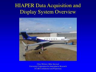
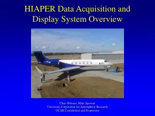
Modular. Flexible, large number of standard interfaces, limited custom interfaces. Network connected (100 BaseT, CAT-6). Remote access to data system and network connected instruments provided by satellite communications. HIAPER Data Acquisition System
Network topology data-net SATCOM display-net recordedinstrument DataServer Display TimeServer DSM Display DSM recordedinstrument non-recordedinstrument non-recordedinstrument
16-bits Sigma-Delta A/D. 24 channels per DSM. Multiple sample rates 1-10,000 Hz. Multiple gains (1, 2, 4, 20), offset option. Temperature compensation. On-board calibration references. Analog Interface
Digital data collection: Serial data: 11 channels asynchronous RS-232, RS-422, RS-485 up to 115K baud. USB 1.1 and 2.0 host control. ARINC-429 12.5K and 100K baud, 4 Rx, 2 Tx. Programmable logic provided for ease of implementing bi-phase, APN-232, pulse counting, etc. Anything I/O card. Parallel data: Flexible 32-bit bi-directional bus with strobes. Configurable as 1x, 4x, 8x, 16x, and 32 bits. Anything I/O card. Pulse counters: 16-bits, double buffered with strobes. Anything I/O card. Digital Interfaces
Computation: Host PC control computer running Linux. DSM processor running RTLinux. Host control computer records data, runs instrument control program, interfaces to satcom, and runs data processing and local display programs. Communications and Control: 100baseT CAT-6 Ethernet data LAN (expandable to 1 GHz). GUI soft-key programmable instrument control program via host control computer. Communications
Time Synchronization and Distribution: GPS time-of-day distributed to DSMs via IRIG-B network from the time server. GPS 1PPS signal distributed to all DSMs. GPS time-of-day distributed via NTP. Display: Data recording, processing and display programs to run on host PC. Timing and Display
ASCII Data Feed(s) via UDP/Ethernet Multiple, configurable. Convertible to RS-232 w/ Digi-One SP box. Data Feeds
Connected to our Data System Softkey buttons available. Stand-alone Use http to clear fire-wall from ground. Request box to display how full your disk is. Remote Instrument Control