Download
1 / 15
150 likes | 258 Vues
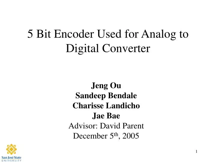
5 Bit Encoder Used for Analog to Digital Converter. Jeng Ou Sandeep Bendale Charisse Landicho Jae Bae Advisor: David Parent December 5 th , 2005. Agenda. Abstract Introduction Why Simple Theory Back Ground information (Brief Review) Summary of Results Project (Experimental) Details

E N D
5 Bit Encoder Used for Analog to Digital Converter Jeng Ou Sandeep Bendale Charisse Landicho Jae Bae Advisor: David Parent December 5th, 2005
Agenda • Abstract • Introduction • Why • Simple Theory • Back Ground information (Brief Review) • Summary of Results • Project (Experimental) Details • Results • Cost Analysis • Conclusions
Abstract • Designed a 5-bit encoder with an area of 482x126 mm2 that will be used to operate a 208 MHz ADC and a power of ~120mW
Introduction • Purpose • To be used to design a 5-bit ADC for EE 198 Senior Project • Using 5-bit Fat-Tree-Encoder • Alternate design option for future EE166 students ( NOR-NOR-NAND vs. OR-OR-OR, INV-AOI-XOR-OR-OR) • Improvement • NOR-NOR-NAND for less logic level and less gates
Previous Work • 2003 Gonzales, et al. Encoder for 6-bit A/D • 2004 Fatimah, et al. Encoding Logic for 5-bit Analog to Digital Converter without Sample and Hold
Encoding of 31 input thermo-code into 5 bit binary number Project Summary Table 1 – Example of 3-bit Conversion • Improvements • Fat-Tree-Encoder composed of NOR and NAND instead of OR and INV gates • Faster than previous projects
Project Detail(Longest Path Calculations) Table 2- Longest Path Calculation Note: All widths are in microns and capacitances in fF
Project Detail(Schematic) Figure 1 – Schematic (XOR-Encoder)
Project Detail(Layout) Figure2 – Layout (XOR-Encoder)
Project Detail(Verification) Figure 5 - LVS Report (XOR-Encoder) Figure 3 DRC (XOR-Encoder) Figure 4 Extraction (XOR-Encoder)
Project Detail(DRC, Extraction, Simulations) Figure 6 – NC Verilog Simulation (XOR-Encoder) Figure 7 – Analog_Environment Simulation (XOR-Encoder )
Cost Analysis • Estimated time spent: • Logic verification : 12 hours • Timing verification : 25 hours • Layout : 40 hours • Post extracted timing : 10 hours
Lessons Learned • Start project on the first day of school. • Also decide on the project on the first day of school • Remote log-in is AWESOME!!! • Say ‘NO’ to drugs and alcohol especially when its FREE.
Summary • Prediction • Refine layout for improvement in organization • Practice makes perfect • Purpose • Simple Theory • Previous Work • Project Summary • Project Details • Results • Schematics • Layouts • Verifications • Simulations • Cost Analysis • Conclusion
Acknowledgements • Cadence Design Systems for the VLSI lab • Synopsis for Software donation • Professor David Parent