Download
1 / 54
1.39k likes | 3.86k Vues
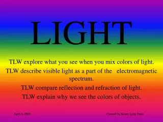
LIGHT : REFLECTION AND REFRACTION. LIGHT. Light is a form of electromagnetic radiation that causes the sensation of sight. It is an indispensable tool without which we cannot explore the colorful beauty of nature.

E N D
LIGHT • Light is a form of electromagnetic radiation that causes the sensation of sight. • It is an indispensable tool without which we cannot explore the colorful beauty of nature. • The blue sky, the rainbow, the red of the sunrise and sunset, the twinkling of stars, the radiance of sparkling diamonds and pearls, and shining color of gems are just some of the natural wonders of light and color.
NATURE OF LIGHT • Light is an electromagnetic wave. • These waves do not require any medium for their propagation. • The wavelength of visible light waves is very small, only about 4 x 10⁻⁷m to 8 x 10⁻⁷m • The speed of light wave depends on the nature of the medium through which they pass. • The speed of light waves in vacuum is very high, being 3 x 10⁸ m/s.
Light provides us means of communication. • The fibre-optic cables consisting of many glass fibres transmit hundreds of telephone conversations over long distances.
REFLECTION OF LIGHT • When light falls on the surface of an object, it may be • i) absorbed ii) transmitted iii) reflected • When light falls on the surface of an object, some of it is sent back. The process of sending back the light rays which fall on the surface of an object, is called reflection of light.
IMAGES • An image is formed when the light rays coming from an object meet ( or appear to meet) at a point, after reflection from a mirror ( or refraction from a lens). • Real Image – If the light rays actually meet after reflection or refraction is called real image. It can be obtained on a screen. • Virtual Image – If the light rays appear to meet after reflection or refraction, then it is called virtural image. It can’t be obtained on a screen.
LAWS OF REFLECTION OF LIGHT • FIRST LAW – The angle of incidence (i) is equal to the angle of reflection (r ) • SECOND LAW – The incident ray, the normal to the mirror at the point of incidence, and the reflected ray, all lie in the same plane.
FORMATION OF IMAGE IN A PLANE MIRROR • The characteristics of image formed in a plane mirror are • i) image is virtual • ii) image is erect • iii) image is of the same size of the object. iv) image is formed as far behind the mirror, as the object is in front of it. • v) image is laterally inverted.
SPHERICAL MIRROR • A spherical mirror is that mirror whose reflecting surface is the part of a hollow sphere of glass. • It is of two types : • i) concave mirrors • ii) convex mirrors
RULES FOR FORMATION OF IMAGE BY SPHERICAL MIRRORS • When an object is placed before a spherical mirror, an image is formed. The image is formed at that point where at least two reflected rays intersect (or appear to intersect). • Now to find out the position of an image formed by a concave mirror, only two rays light is required. We use those rays whose path is certain, the diagram formed in this way is called as ray diagram. Continued…
To draw ray diagram, the following rules are used: • i) A ray of light parallel to the principal axis of the mirror, passes through the focus after reflection from the mirror. • ii) A ray of light passing from the center of curvature of the mirror is reflected back along the same path. • iii) A ray of light passing through the focus of a concave mirror becomes parallel to the principal axis. An image of any point is formed at that point where at least two reflected rays intersect or appear to intersect.
NEW CARTESIAN SIGN CONVENTION Objects on the left M Y A Direction of Incident light Height upwards (+ve) Direction against Distance along Incident light (+ve) Incident light (-ve) P X’ X B B’ Height downwards (-ve) Height downwards (-ve) N A’ Y’ Height downwards (-ve)
MIRROR FORMULA A M h B’ B C F P h’ f A’ u v N R Fig 2.3
FORMATION OF IMAGE BY CONVEX MIRROR M A D E A’ B’ F C B P N
We will now obtain a relation between the object-distance (u), the image –distance (v) and the focal length (f) of the spherical mirror having small aperture (much less than the radius of curvature (R). This relation is called Mirror Formula.It remains the same in all types of physical situations, whether the image is real or virtual
We now derive the mirror formula for a concave mirror producing a real image in fig 2.3. • When the object AB is of size or height (h) is placed on the left in front of the concave mirror MN, beyond its centre of curvature C, The image formed is real, inverted and diminished in size (h’)
Using the New Cartesian Sign Convention, we have • Object distance = PB = - u • Image distance = PB’= -v • Focal length = PF = -f • Radius of curvature = PC = -R • Now in fig 2.3 , the right angle triangles ∆ A’B’P and ∆ ABP, are similar, so that • A’B’ PB’ -v v AB PB -u u 3,1
Similarly in the right angled triangles, ABC and A’B’C’ are similar, so that • A’B’ CB’ • AB CB • As we measure all distances from the pole P, we have • CB’ = PC – PB’ • CB = PB – PC • Using equation 3.2 we get • A’B’ PC – PB’ (-R)-(- v) -R + v • AB PB – PC (-u)–(-R) -u + R 3.3
Comparing Eqs. (3.1) and (3.3), we get • - R + v v • - u + R u • Or, uR + vR = 2uv • Dividing both sides by uvR, we get • 1/v + 1/u = 2/R -------------- (3.4) • When the object AB is taken at a very large distance ( at infinity), as shown the image is formed at the focus F. Thus, when u =∞ , v = f, putting the values in eq 3.4 , we get • 1/f + 1/∞ = 2 / R or f = R/2 ------ (3.5)
MAGNIFICATION • The ratio between the height of the image produced by the spherical mirror to the height of the object is called linear magnification. Height of the image Linear magnification = -------------------------- Height of the object hi M = --------- = v/u ho
REFRACTION OF LIGHT AND ITS LAWS • the ratio of sine of angle of incidence to the sine of angle of refraction is constant. Thus, angle of incidence I and the angle or refraction r are related as Sin i ------- = n21 sin r n21 is a constant and is called the refractive index of second medium with respect to first medium. It is also known as Snell’s law of refraction. • ii) The incident ray, the refracted and the normal at the point of incidence lie in the same plane.
REFRACTIVE INDEX • Ans:- For two media and for a light of a particular color, the ratio of sine of incidence angle and sine of refraction angle is called refractive index of second medium with respect to first. Sin i --------------------- = n21 sin r • if motion of light is in reverse direction means from medium 2 to medium 1, refractive index is reversible n12 = sin r/ sin i = 1/n21 • if velocity of light is v1 in first medium and v2 in second medium, • n21 = velocity of light in first medium(v1)/ velocity of light in second medium (v2)
Refractive index of water is 4/3 and glass is 3/2 with respect to air. What is refractive of glass with respect to water. Ans;- refractive index of air , n1 = 1.00 • Thus, refractive index of water w.r.t. air, n21 = n2 = 4/3 • Refractive index of glass w.r.t. air = n31 = n3 = 3/2 • Refractive index of glass w.r.t water = n32 • n32 = n31 x n12 = n31/ n21 = n3/n2 = (3/2)/(4/3) = 9/8 = 1.125
RULES FOR IMAGE FORMATION IN SPHERICAL LENSES • A ray from the object parallel to the principal axis after refraction passes through the second principal focus F2 ( in a convex lens) or appears to diverge ( in a concave lens) from the first principal focus F1 • A ray of light passing through the first principal focus ( in a convex lens), or appearing to meet at it ( in a concave lens) emerges parallel to the principal axis after refraction.
3) A ray of light passing through the optical centre of the lens, emerges without any deviation after refraction.
IMAGE FORMATION IN CONVEX LENS • CONVEX LENS M C A B’ B O 2F1 F1 F2 A A’ N
LENS FORMULA M C A B’ B O 2F1 F1 F2 2F2 A’ N
Here object distance = OB = -u • Image distance = OB’ = v • Focal length = OF2= f • AB = OC • ∆ ABO ~ ∆ A’B’O are similar • A’B’/AB = OB’/OB = v/-u ……….eq. –(i) • Similarly ∆ OCE2 ~ ∆A’B’F2 • A’B’/OC = F2B’/OF2, As AB = OC, then • A’B’/AB = F2B’/OF2 = ( OB’- OF2)/OF2 = (v-f)/f • ……..eq. – (ii)
From eq. (i) & (ii) we get, -v/u = v-f/f • On cross multiplication and dividing both sides by uvf, we get, 1/v – 1/u = 1/f
IMAGE FORMATION IN CONCAVE LENS F1 2F1 O Object is at infinity and the image is at F1
When the object is between O and Infinity A A' B’ B F1 2F1 O
POWER OF A LENS • The power of a lens is a measure of the degree of convergence or divergence of light rays falling on it. • The power is defined as the reciprocal of its focal length (f) as • P = 1/f • The SI unit of power of a lens is dioptre denoted by symbol D. • If f is expressed in metres so that 1 D= 1m-1
Retina Pupil Iris Aqueous humour Vitreous humour Cornea Lens Cilliary muscle Suspensory ligament Choroid Blind spot Optic nerve fovea Human Eye Different parts of Human eye are as follows:-
SIMPLE MICROSCOPE • A simple microscope is a convex lens of short focal length. It is also called magnifying lens. • The convex lens is held near the object to be magnified, such that it is in between the optical centre and principal focus, but close to principal focus. • An erect virtual and enlarged image A1B1 is formed at the least distance of distinct vision as shown in fig. Next page.
Magnification • Size of the image • M = Size of the object • = Distance of the image from eye • Distance of object from eye • M = A1B1/AB = D/f ( because eye is held close to lens) , Thus, if a convex lens of focal length 6.25 cm is used its magnification is • m = D/f = 25 cm/ 6.25 cm = 4
COMPOUND MICROSCOPE • Construction – A compound microscope consists of two metallic tubes such that they can easily slide in one another. • The tubes are blackened from inside to prevent any internal reflection. • On the side of the smaller tube a convex lens of very small focal length called objective lens is fitted which faces towards the object.
On the side of bigger tube, another convex lens of larger focal length is fitted. This lens is called eye lens. • Working – A tiny object AB is placed in between F0 and 2F0 of the objective lens, when it forms a real, inverted and magnified image A1B1 on the other side of objective lens, i.e. within the tubes.
Now the eye lens tube is moved backward or forward, such that the real image A1B1 falls between the principal focus (Fe) and its optical centre (O) of the eye lens. • The rays starting from the real image A1B1 on passing through the eye lens give rise to a divergent beam of light. • When these divergent rays are received by the eye, they appear to come from the points A2 and B2. • Thus A2B2 is the virtual, but highly enlarged image of the object AB.
The image formed here is inverted with respect to the object. • However, this does not make any difference as most of the biological specimens seen under the microscope are round and oval or not very well defined in shape.
magnification • The magnifying power of a compound microscope is the ratio between the final size of the virtual image to the actual size of the object. • M = (D x L) where D = least distance of • F0 x fe distinct vision, L= tube length, f0 = focal length of objective, • fe = focal length of eyepiece.
ASTRONOMICAL TELESCOPE • Astronomical telescope is an optical device used to for seeing heavenly bodies such as the stars, the Sun, the Moon, etc, closely. • Construction – It consists of two convex lenses, i.e. an objective lens of very large focal length and eye lens of very small focal length. • The two lenses are mounted on separate tubes which can slide in one another.
working • The rays coming from a distant heavenly body are parallel to one another, but generally not parallel to the principal axis. • These rays, on passing through the objective lens, suffer refraction and hence, converge in the plane of the principal focus to form a real, inverted and diminished image AB of a distant body.