Download
1 / 1

E N D
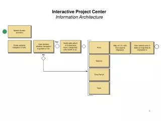
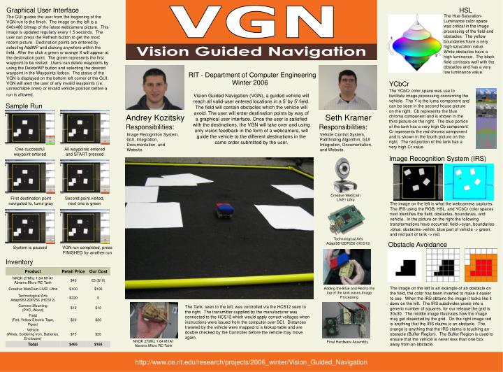
Graphical User Interface VGN HSL The Hue-Saturation-Luminance color space was critical in the image processing of the field and obstacles. The yellow boundaries have a very high saturation value. White obstacles have a high luminance. The black field contrasts well with the obstacles and has a very low luminance value. The GUI guides the user from the beginning of the VGN run to the finish. The image on the left is a 640x480 bitmap of the latest webcamera picture. This image is updated regularly every 1.5 seconds. The user can press the Refresh button to get the most recent picture. Destination points are entered by selecting AddWP and clicking anywhere within the field. After the click a green or orange X will appear at the destination point. The green represents the first waypoint to be visited. Users can delete waypoints by using the DeleteWP button and selecting the desired waypoint in the Waypoints listbox. The status of the VGN is displayed on the bottom left corner of the GUI. VGN will alert the user of any invalid waypoints (i.e. unreachable ones) or invalid vehicle position before a run is allowed. Vision Guided Navigation RIT - Department of Computer Engineering Winter 2006 YCbCr The YCbCr color space was use to facilitate image processing concerning the vehicle. The Y is the luma component and can be seen in the second house picture on the right. Cb represents the blue chroma component and is shown in the third picture on the right. The blue portion of the tank has a very high Cb component. Cr represents the red chroma component and is shown in the fourth picture on the right. The red portion of the tank has a very high Cr value. Vision Guided Navigation (VGN), a guided vehicle will reach all valid-user entered locations in a 5' by 5' field. The field will contain obstacles which the vehicle will avoid. The user will enter destination points by way of a graphical user interface. Once the user is satisfied with the destinations, the VGN will take over and using only vision feedback in the form of a webcamera, will guide the vehicle to the different destinations in the same order submitted by the user. Sample Run Andrey Kozitsky Seth Kramer Responsibilities: Responsibilities: Image Recognition System, GUI, Integration, Documentation, and Website. Vehicle Control System, Pathfinding Algorithm, GUI Integration, Documentation, and Website. One successful waypoint entered All waypoints entered and START pressed Image Recognition System (IRS) Creative WebCam LIVE! Ultra First destination point navigated to, turns gray Second point visited, next one is green The image on the left is what the webcamera captures. The IRS using the RGB, HSL, and YCbCr color spaces next identifies the field, obstacles, boundaries, and vehicle. In the picture on the right the following transformations have occurred: field->cyan, boundaries->blue, obstacles->white, blue part of vehicle -> green, and red part of tank -> red. Technological Arts Adapt9S12DP256 (HCS12) Obstacle Avoidance System is paused VGN run completed, press FINISHED for another run Inventory The image on the left is an example of an obstacle on the field, the color has been inverted to make it easier to see. When the IRS obtains the image it looks like it does on the left. The IRS subdivides pixels into a generic number of squares, for our release the grid is 30x30. The middle image illustrates how the image may get dissected by the grid. On the right image red is anything that the IRS claims is an obstacle. The orange is anything that the IRS claims is touching an obstacle (Buffer Region). The Buffer Region is used to ensure that the vehicle is never less than one box away from an obstacle. Adding the Blue and Red to the top of the tank eases Image Processing The Tank, seen to the left, was controlled via the HCS12 seen to the right. The transmitter supplied by the manufacturer was connected to the HCS12 which would apply correct voltages when instructions were issued from the computer over SCI. Distances traveled by the vehicle were mapped to a lookup table and are double checked by the Controller before the vehicle may move again. NKOK 27Mhz 1:64 M1A1 Abrams Micro RC Tank Final Hardware Assembly http://www.ce.rit.edu/research/projects/2006_winter/Vision_Guided_Navigation