Download
1 / 31
310 likes | 412 Vues
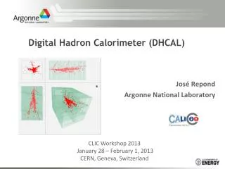
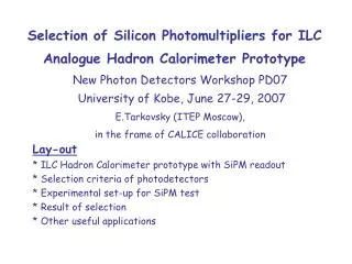
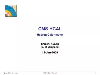
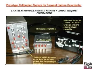
Construction and Testing of a Digital Hadron Calorimeter Prototype. For TIPP 2011. Kurt Francis ANL_HEP. K L. HCAL. ECAL. π +. γ. Need new approach. Particle Flow Algorithms. The goal : a detector that achieves 30%/ √E jet energy resolution

E N D
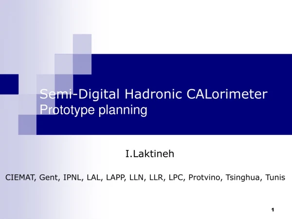
Construction and Testing of a Digital Hadron Calorimeter Prototype For TIPP 2011 Kurt Francis ANL_HEP
KL HCAL ECAL π+ γ Need new approach Particle Flow Algorithms The goal: a detector that achieves 30%/√E jet energy resolution Favored method is to use particle flow algorithms that measure charged particles with tracker and measure neutral particles with calorimeter Requires: Excellent tracker and high B – field And a dense calorimeter also inside coil with high granularity to distinguish individual particle showers in jets and assign to charged or neutral parent Argonne’s solution: a digital hadron calorimeter (DHCAL) using RPC chambers and 1 cm x 1 cm readout pads with single bit readout hit counting sufficient 18%/√E Required for 30%/√E DHCAL Construction
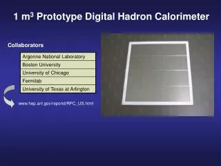
1 m3 – Digital Hadron Calorimeter Physics Prototype Description Readout of 1 x 1 cm2 pads with one threshold (1-bit) →Digital Calorimeter Layers inserted into the existing CALICE Analog (scintillator) HCAL and TCMT structures 38 layers in DHCAL and 14 in tail catcher (TCMT), each ~ 1 x 1 m2 Each layer with 3 RPCs, each 32 x 96 cm2 ~480,000 readout channels Purpose Validate DHCAL concept Gain experience running large RPC systems Measure hadronic showers in great detail Validate hadronic shower models (Geant4) Status Started construction in 2008 Completed in January 2011 Test beam runs started in Oct. 2010 at Fermilab More test beam runs through rest of year Analysis on-going DHCAL Construction
Collaboration and Responsibilities DHCAL Construction ALCPG 2011 - Jacob Smith 4
Pad board Glass Frame Frame Glass Pad board Frame Frame Glass RPC Construction RPC design 2 – glass RPCs (chosen for construction) 1 – glass RPCs (developed at Argonne) Gas gap size 1.1mm Total RPC thickness < 3.4mm Dead area ~5% (frame, spacer) RPC concept High voltage across gas(Freon+Iso-butane+SF6) Ionization is amplified by avalanche effect Signal detected at pad boards Chambers needed ~114 for DHCAL + 42 for TCMT + spares at the end, produced ~ 205 RPC’s Assembly steps Spraying of glass plates with resistive paint Cutting of frame pieces Gluing frame Gluing glass plates onto frame Mounting of HV connection, etc. DHCAL Construction
Spraying of the glass sheets Challenge Produce a uniform layer with R□ = 1 – 5 MΩ value affects pad multiplicity value only critical for thin plate, thick plate can be lower/higher New paint (artist paint) identified Reasonably cheap Non toxic 2 component mixture (BLACK and GREEN) Needs to be sprayed (built a spraying booth) Production Has been a struggle Poor uniformity in a single plate Mean value not well controlled from plate to plate Low yield: ~ 60% pass quality cut Slow – barely match RPC assembly speed at the end, it worked out MΩ/□ DHCAL Construction
RPC Assembly Cutting frames Dedicated (adjustable) cutting fixture Cut length to .2mm precision Drill holes Tooling designed at ANL Assembly Dedicated gluing fixture Frame/gap glued to ~0.1mm precision Very time consuming process: ~1 RPC/day/tech, 3 RPC produced/day Production 205 final RPC completed only ~10 not usable (due to glass broken or quality issues) DHCAL Construction
1 mil = 25 μm Quality Assurance Pressure tests Test with 0.3 inch of water pressure Pass if pressure drop < 0.02 inch in 30 seconds Chambers not passing 1st test are repaired All repaired chambers passed 2nd test Gap size measurement Thickness of all chambers measured along the edges (since glass is very uniform → measure of gap size) Gap sizes at edges within 0.1 mm (central region uniform due to fishing lines) Corners typically thicker (up to 0.3 – 0.4 mm) (only affects very small region) > Only ~5 RPC’s have low efficiency regions at corner(s) or along side(s), due to larger gap at those places, all replaced from prototype stack HV tests Tests up to 7.0 kV before placing readout board on top (operating voltage is 6.3 kV) DHCAL Construction
Cosmic Ray Test Stand Up to 9 RPCs tested at once Testing of early FE board versions First batch of chambers Chamber characterization using cosmics and noise Noise measurements High voltage scans from 5.8 to 6.8 kV Triggered, trigger-less operation DHCAL Construction 9
Cosmic Ray Test Stand (cont.) Triggered Data: Standard tests Trigger-less Mode Analyze Cosmic Rays Angle of Incidence Dependence! DHCAL Construction 10
Readout system overview Data Collectors – Need 10 VME Interface master IN Ext. Trig In To PC • Timing Module • Double Width • - 16 Outputs 6U VME Crate Data Concentrator Front End Board with DCAL Chips & Integrated DCON Chambers – 3 per plane Data Collectors – Need 10 VME Interface master IN Ext. Trig In To PC • Timing Module • Double Width • - 16 Outputs 6U VME Crate Communication Link - 1 per Front-End Bd Square Meter Plane DHCAL Construction
The DCAL Chip Developed by FNAL and Argonne Input 64 channels High gain (GEMs, micromegas…) with minimum threshold ~ 5 fC Low gain (RPCs) with minimum thrshold ~ 30 fC Threshold Set by 8 – bit DAC (up to ~600 fC) Common to 64 channels Readout Triggerless (noise measurements) Triggered (cosmic, test beam) Versions DCAL I: initial round (analog circuitry not optimized) DCAL II: some minor problems (used in vertical slice test) DCAL III: no identified problems (final production: used in current test beam) Production of DCAL III 11 wafers, 10,300 chips, fabricated, packaged, tested Hits/100 tries Threshold (DAC counts) DHCAL Construction Threshold (DAC counts) 12
FrontEnd/DCON board + Pad board Build FE and pad boards separately to avoid blind and buried vias (cost and feasibility issue) Each board contains 1536 channels and 24 ASICs The data concentrator is implemented into the same board Glue the two boards together with conductive epoxy FE board need to pass computer test before gluing Extensive tests (S-curves, noise rates…) 3 – 6 hours/board Accepted boards with less than 4/1536 dead channels ASIC Front-End PCB Communication Link Conductive Epoxy Glue Pad Board Signal pads Mylar 8.6 mm Resistivepaint 1.1mm glass 1.2mm gasgap HV Fishing line spacers 1.1mm glass Resistive paint Mylar Aluminum foil DHCAL Construction
Gluing fixture for Pad- and FE-boards Goal:1536 glue dots on contacts in less than 3 hours Fixture Designed, built and commissioned Production ~25 minutes needed/board can glue > 10 boards/day at the end: 300+ FE board fabricated/tested/glued DHCAL Construction
Power supply systems Low voltage system High voltage system Back end electronics Timing and Trigger Module (TTM) Data Collector DCOL Gas System DHCAL Construction
Cassette Assembly Assembly - Cassette is compressed horizontally with a set of 4 (Badminton) strings - Strings are tensioned to ~20 lbs each, very few broken strings - ~45 minutes/cassette - steel and copper plates Cassette Testing - Cassettes were tested with CR before shipping to FTBF 38+14 cassettes assembled DHCAL Construction
Transportation to FNAL and installation DHCAL Construction
Installation into CALICE structure at FNAL DHCAL Construction 18
Installation complete! DHCAL Construction
Cabling up 12 hours of hard work (350,000 readout channels for the DHCAL alone!) DHCAL Construction
The RPC DHCAL Testbeam Story DHCAL Construction 21
2 5 3 4 1 6 7 8 DHCAL Construction 24
First beam: muons One muon Three muons Four muons A lot of muons DHCAL Construction
Next: pions 60 GeV pions measured in DHCal 60 GeV Pions GEANT4 simulation + RPC response simulation You’ve seen these simulation pictures many times… DHCAL Construction Now, the real thing!
And also positrons 32 GeV 25 GeV 20 GeV 16 GeV DHCAL Construction 12 GeV
And occasionally, neutral hadron DHCAL Construction
Summary • The construction of the DHCAL prototype (+TCMT) is complete • Test beam at Fermilab started last Oct. • DHCAL prototype (+TCMT) works extremely well • A lot of good data collected, analysis is on-going • First look of the data is very encouraging! • More test beam/more data is on the way • 5 to 6 more weeks in May/June • Project led by Argonne • Involves local Universities • Many students involved in all phases: construction, operation and analysis DHCAL Construction