Download
1 / 23
4.05k likes | 9.6k Vues
Electrical Earthing. D.K.Pathirana. Applications of earthing. • Protect human against lightning and earth fault condition • Protect the premises against lightning and earth fault condition • Provide low resistance and safe path for lightning and fault current

E N D
Electrical Earthing D.K.Pathirana
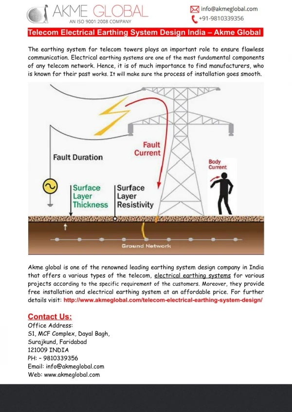
Applications of earthing • Protect human against lightning and earth fault condition • Protect the premises against lightning and earth fault condition • Provide low resistance and safe path for lightning and fault current • All metallic enclosure and extraneous conductive parts are at equipotential • LV System Earth
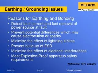
Functions of Earthing Equipment Earth : Path for fault current, lower touch voltage, protection against electric shock Lighting Earth : Low resistance path to diverse the current under lightning attack. Telecom Earth : Signal Earth, reduce noise and interference, stabilize DC supply voltage and prevent electric shock Computer Earth : reduce interference, maintain supply voltages
Two classes of protection Class I protection – use of barrier/insulation and connection of protective conductor to equipment metallic enclosure in order to protect against electric shock Class II protection – beside of the basic insulation, addition layer of insulation apply to the enclosure. Therefore no extraneous conductive part. The additional layer is independent to the basic insulation so that under failure of basic insulation, it offers additional protection
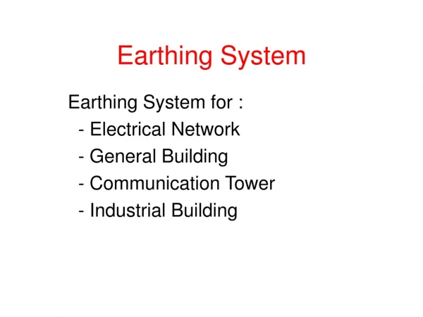
Types of Earthing • Supply System – Neutral Earth • System Earth • Electrical Safety Earth • Lightning Earth • Generator Earth • Protection Earth (i.e. surge arrestor) • Telecom / Computer Earth • Shielding Earth • Integrated Earthing System (Advocated) • Electrostatic Earth (Clean Room / Hospital)
Earthing Arrangements • TN System • TNS System • TN C S System • TN C system • TT System • IT System
Factors affect to the earth impedance • Soil • Weather • Electrode type • Electrode size • Near by utilities • Electrode in parallel • Distance between electrode
Soil Resistivity • The resistivity of earth may vary over extremely wide limits, depending on the composition of the soil and the moisture content. Factors that affect resistivity • Type of earth (eg, clay, loam, sandstone, granite) • Stratification; layers of different types of soil (eg, loam backfill on a clay base) • Moisture content • Temperature • Chemical composition and concentration of dissolved salt
WENNER method ρw= 2 π d RS-ES
SCHLUMBERGER method ρs = ( π (d2 – A2/4) RS-ES ) / A
Types Of Earth Electrodes • Solid Copper • Copper clad steel rod ( copper shrunk onto the core) • Copper Bonded steel core (coper is molecularly bonded to nickel plated steel rod)
Earth Resistance Of An Electrode • soil exhibits a resistance to the flow an electrical current • not an “ideal” conductor • resistance (can never be zero) between the earth electrode and “true Earth”. • The resistance between the earth electrode and “true Earth”
Rods Driven Vertically Into The Ground Rg = (𝞺/2𝞹L)[ln(8L/d)-1] where, ρ - Soil Resistivity in Ωm L - Buried Length of the electrode in m d - Diameter of the electrode in m
Combined Resistance Of n No Of Electrodes In which Where R=resistance of one rod Ω S = distance between adjacent rods m ρ = resistivity of soil Ω-m λ =is a factor selected from Table 2 or 3 of BS 7430 ‘n is the no of electrodes as given in Tables 2 and3
Resistance Of A Vertical Electrode With Infill Of Bentonite Or Concrete Where, 𝞺c – resistivity of the infill material d – diameter of electrode in m D – diameter of infill L – driven length of electrode
Approximate Resistance for a Strip or a round conductor Where , L – length of the strip ‘h - the depth buried w - width of the strip P and Q are coefficient for strip or round conductor in Table 5