Download
1 / 31
310 likes | 406 Vues
CLIC Drive beam RF system including phase and intensity stabilisation systems Erk Jensen, BE-RF. 4th CLIC Advisory Committee (CLIC-ACE) 26-May-2009. What I’ll talk about:. Which size and how many power sources? Which size modulators? The issue phase jitter and ideas to address it.

E N D
CLIC Drive beam RF systemincluding phase and intensity stabilisation systemsErk Jensen, BE-RF 4th CLIC Advisory Committee (CLIC-ACE) 26-May-2009
What I’ll talk about: • Which size and how many power sources? • Which size modulators? • The issue phase jitter and ideas to address it. What I’ll not talk about: • Thanks to CTF3, many issues have already been addressed and feasibility demonstrated: e.g. full beam loaded operation, beam pulse compression ... I acknowledge: • I report on work of many others, in particular D. Schulte, A. Anderssonand in Jonathan Sladen. Jonathan passed away last week – we are all immeasurably saddened about this. 4th CLIC Advisory Committee (CLIC-ACE)
CLIC Drive Beam RF System • The CLIC Drive Beam RF system as such is not considered a feasibility issue and consequently has not been designed. • However, some parameters are unprecedented and require attention; we are only starting to address theseissues: • Very large total power (≈23 GW peak, 170 MW average) • What power source? • Optimum size (and number) of the power source “modules”? • related with the above: reliability, operability, maintainability, noise! • Phase stability (jitter <50 fs) ; phase errors are multiplied with combination scheme. Origins of phase noise and their propagation through the klystrons, accelerating structures and combining scheme. Can this be done? Mitigation? • Overall efficiency! Two-beam scheme has more stages than single-beam scheme! • Cost! Considering the above, the drive-beam generation scheme and its RF system are a non-negligible cost driver. 4th CLIC Advisory Committee (CLIC-ACE)
Reminder: what does CLIC need? • Recent parameter changes: • Nov. 2006: 937 MHz (30 GHz/32) 1.333 GHz (12 GHz/9) • Sep. 2007: 1.333 GHz 999.52 MHz (12 GHz/12) • Total peak RF power required per linac is about 11.5 GW (from 4.21 A · 2.38 GV / 93.5% / 93.2%). • With a rep. rate of 50 Hz and an RF pulse length of – say – 150 μs (total CLIC length/c), we get: • Duty factor 150 μs · 50 Hz = 0.75 % av. power 86 MW *)! • Of major importance for the RF power source in the specifications are • the phase stability, • the power conversion efficiency. *) See next page 4th CLIC Advisory Committee (CLIC-ACE)
Average powers from CLIC 2008 Parameters 4th CLIC Advisory Committee (CLIC-ACE)
Klystrons or something else? • Could it be magnetrons? • Injection-locked oscillators • Potentially better efficiency, but phase noise requirement would either be a show-stopper or at least require longer RF pulses for phase to stabilize and thus decrease the effective efficiency. no • Could it be IOT’s? • Present day IOT’s are around 100 kW. They’re less reliable today. They have much less gain! I don’t see a clear advantage for the R&D required.no – maybe reconsider later • Pencil-beam klystrons? • Why not? You need a much larger number (say 10’000) but that would be extremely well studied and reliable objects. Sprehn noted the advantages in 2004 (1.7 MW tubes à 27.5 k$): • Several tube companies would participate. Competition combined with quantity would drive costs down. • Simplified cavity waveguide feeds (maybe not true in our case) • Graceful system degradation (!) • Higher reliability • For n tubes replacing 1, uncorrelated noise decreases by factor √n! yes • Multi-beam klystron? • Definitely the closest to existing, ready-to-use technology! I would put my money on these! Say 12 beams, 140 kV, 10 to 15 MW.yes • Sheet-beam klystrons? • They promise to be much cheaper for larger quantities, but there is no demonstration today that would support this claim yes - later 4th CLIC Advisory Committee (CLIC-ACE)
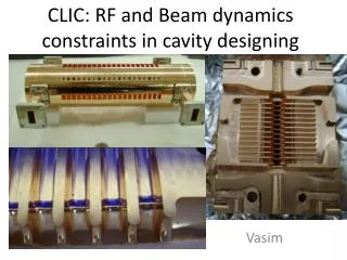
Existing: ILC 1.3 GHz MBK’s (10MW, 1.5 ms, 10 Hz) • CPI: VKL-8301B (6 beam): 10.2 MW, 66.3 %, 49.3 dB gain • Thales: TH 1801 (7 beam): 10.1 MW, 63%, 48 dB gain • Toshiba: E3736 (6 beam): 10.4 MW, 66 %, 49 dB gain 2. 1. 3. 4th CLIC Advisory Committee (CLIC-ACE)
Existing idea for a high power, high efficiency MBK: • Cf. Jensen, Syratchev: “CLIC 50 MW L-Band Multi-Beam Klystron”, CLIC-Note-640 • The main idea: use a mode like the one depicted as #4 (whispering gallery mode) for many beams; the advantage of this mode: It can be made very pure! • The problem: This device became reallybig: how do you braze this? Imagine alittle problem in one of the ≈22 beams! • There is a study ongoing in collaborationwith Thales and Lancaster University(PhD work). 4th CLIC Advisory Committee (CLIC-ACE)
What’s in the 2008 parameter list • Given the total peak power, it had been assumed that 33 MW peak could be made available at the input of each accelerating structure. This resulted in 326 klystrons and 326 accelerating structures per linac. • The accelerating structures were scaled from the existing 3 GHz structures and not optimized for 1 GHz. • The number of cells is then adjusted to be fully beam-loaded for the nominal current and power. • Keeping the beam current at its nominal value of 4.21 A, here the input power requirements for structures with different cell numbers: • Importance of the group delay: the structure will “filter out” noise from the klystron and from the beam. 4th CLIC Advisory Committee (CLIC-ACE)
Input power for full beam loading for different cell numbers present “nominal” ≈ 28.3 kW · ncell2 4th CLIC Advisory Committee (CLIC-ACE)
Conclusion (from this table) • The number of cells can be adapted to the available RF power. • Shorter accelerating structures are more efficient (less ohmic losses – small effect) • With shorter structures, the linac overall length gets large. • These are preliminary structures, just scaled from CTF3. As a consequence, the beam aperture is a factor 3 larger than at 3 GHz (34 mm -> 102 mm, while the beam current is only 20 % larger (3.5 -> 4.2 A). Re-optimization of the accelerating structures is in progress. 4th CLIC Advisory Committee (CLIC-ACE)
Efficiency • The CLIC 2008 Parameters assume a tube efficiency of 70%, existing tubes reach 66%. For the CDR, 66% should be used. • It is generally accepted that maximum obtainable efficiency is a function of the perveance I/V3/2. Using an empirical model, here is what one could expect (numbers for 13 MW DC): • For practical reasons, the voltage should be kept moderate (say below 140 kV). • To limit the complexity, the number of beamlets should remain reasonable. • I marked a point which I find interesting: 12 beams, 140 kV; it could reach above 70%. 84 % klystron DC voltage [V] 140 kV, 12 beams 82 % 80 % ILC klystrons 78 % 70 % MBK # of beamlets 4th CLIC Advisory Committee (CLIC-ACE)
How does the cost of a klystrons scale with peak power? • Probably: cost per klystron proportional to (peak power)1/2 (*) • At a level of around 15 MW peak, the slope will become steeper due to increased system complexity. • This leads to the following model: • Blue: present state of the art • Red: assuming a major investment into the development of a dedicated 30 MW tube (*) rule of thumb given by T. Habermann/CPI. Rees/LANL estimates P0.2 for 0.5 to 5 MW tubes. 4th CLIC Advisory Committee (CLIC-ACE)
Cost per MW • Using the above model, here’s the klystron cost per MW (peak) • Blue: present state of the art • Red: assuming a major investment into the development of a dedicated 30 MW tube 4th CLIC Advisory Committee (CLIC-ACE)
Tube lifetime • In spite of its price, a klystron is a consumable! • A klystron has a finite lifetime; this will also depend on its internal complexity (and on the peak power!). • The lifetime will depend on many parameters, primarily the current density, but here’s one estimate ... What about an MBK?: is the tube dead if one of n beams fails? If the design is good, the n beams would fail at around the same time ... 4th CLIC Advisory Committee (CLIC-ACE)
Cost per 100,000 operating hours and per MW • Even if this model may be wrong, there will be a cost per MW and per operating hour: With the above model, this becomes: • Blue: present state of the art • Red: assuming a major investment into the development of a dedicated 30 MW tube 4th CLIC Advisory Committee (CLIC-ACE)
Conclusion (from the cost per tube per operating hour) • The lifetime model presented here may be wrong; the scaling for the unit cost may be wrong, but for a correct cost estimate, both these influences must be included. • Assuming that the models used above are somehow reasonable, the optimum size of an individual tube would be not significantly above 10 MW. This conclusion may change depending on a better model. • It may also change after dedicated R&D, but in my opinion this R&D should rather address the reliability, cost and lifetime than the peak power. • Anticipating from the phase noise analysis: • The klystron phase pushing gets better for shorter tubes and higher voltage (see below) • individual sources instead of 1 will decrease the (uncorrelated) noise by a factor 4th CLIC Advisory Committee (CLIC-ACE)
Concerning modulators • R&D is going on for ILC, SPL, ... we should take full advantage! • Our CERN modulator experts explain: • A classical “bouncer” type modulator for a size of 12 kV, 2 kA can be considered feasible. • It would look like this (just the topology, picture taken from ILC): • A larger modulator would combine a number of these; it’s cost would scale at best linearly with peak power – the “modular modulator” – no saving from making it bigger. This (20 MW peak or so) seems to be the natural module size. A modulator with 3 modules would cost around 1 MCHF. • The numbers given here would be consistent with a 15 MW MBK. 12 kV, 2 kA 140 kV, 160 A 4th CLIC Advisory Committee (CLIC-ACE)
Modulator This is some really big object! Some ILC examples: IGCT stack: HVPS and pulse forming unit: Pulse transformer: ILC estimate: 300 ... 400 k$/unit Commercial modulator 20 MW, average power around a factor 10 too small. One would need 1 of those every 2 to 3 m for the total length of the DBL! 4th CLIC Advisory Committee (CLIC-ACE)
Conclusion (modulators) • Base line: bouncer type modulator is quasi “commercial”. • 12 kV/2kA is a natural module size (24 MW DC); • pulse transformer 12:1, 140 kV/160 A • Larger modulators of this type would not be cheaper per MW. • Modulators of other types require R&D! • With a 70% efficient klystron, this would correspond to15 MW RF. • Anticipating from phase noise analysis: • Feed-forward to compensate for systematic voltage variation (droop) must be provided! • Stabilisation of the voltage to the 10-5 level is hard! • Again: the noise from more, smaller modulators will add only as . 4th CLIC Advisory Committee (CLIC-ACE)
Phase stability/stabilisation • Drive beam phase jitter leads to luminosity drop. • Δφat 1 GHz causes 12 Δφat 12 GHz! • Any R56 transforms drive beam energy jitter to phase jitter. • With full beam loading, drive beam current error transforms to energy error (and then phase error). • Requirement (order of magnitude): drive beam phase jitter <0.02° (3.5E-4, 50 fs) drive beam energy jitter <O(1E-4) (With a feed-forward, this may be relaxed by a factor 10!) • Accelerating structures and recombination scheme act as filters for the noise. 4th CLIC Advisory Committee (CLIC-ACE)
Origins of noise • We look at “noise”, which is meant to include both amplitude and phase noise. The difference is the correlation between sidebands. • Strictly speaking, noise is characterized with its spectral power density S (W/Hz), so the jitter specification should be called “integrated jitter” • Principal origins of noise: • Drive beam Gun: intensity variations • Phase reference generation and distribution *)! • SH pre-buncher (500 MHz, flips phase every 244 ns ! creates also systematic error at 2.05 MHz!) • Klystrons (modulator, temperature, drive ...) • Propagation of noise: • Noise propagates like any other signal, the analysis is similar (uses ) *) See next page 4th CLIC Advisory Committee (CLIC-ACE)
Global timing distribution: ongoing R&D efforts Two major R&D efforts are ongoing on the development of optical clock systems: ... Both systems are fully consistent: each of them fulfils the requirements for a complete fs timing system. [M. Ferianis, "Timing and Synchronization in Large Scale Linear Accelerators", LINAC 2006, Knoxville, Tennessee USA] The distribution of ultrafast optical pulse trains across 300 meters of fiber with sub-femtosecondtiming jitterand83 fsof drift over 25 hours, as measured between the outputs from two independent links, is demonstrated. [J. A. Cox et. al, “Sub-femtosecond Timing Distribution of an Ultrafast Optical Pulse Train over Multiple Fiber Links”, OSA / CLEO/QELS 2008]
Alternate CLIC timing scheme Commercially available Sapphire Loaded Cavity Oscillator with 3…5 fsintegrated phase noise. Use low frequency global timing signal to compensate for slow frequency drifts. Use outgoing main beam for precision synchronization of phase. I.e. measure average phase between RF extracted from the outgoing main beam, and subtract from the later measurement for the drive beam phase. See also: A. Andersson, J.P.H. Sladen: “Precision beam timing measurement system for CLIC synchronization”, EPAC 2006; A. Andersson, J.P.H. Sladen: “First tests of a precision beam phase measurement system in CTF3”, PAC2007
High precision phase detector • For this feed-forward scheme: in order to correct, first you have to detect to at least the same precision! • The phase monitors are part of the work-package “NCLinac” inside the European FP7 project “EuCARD”. • Collaboration CERN, PSI, INFN/LNF • Estimated resources: 5.1 FTE-y, 0.95 M€. Here an excerpt from the task definition: ... a monitor able to detect the longitudinal position of the bunches with a resolution of the order of 20 fs. The coupling impedance of the monitor has to be very low due to the high beam current. RF noise and wake fields in the beam pipe must not affect the measurement and have to be rejected by proper designed filters. This device will find applications in other machines where precise high frequency beam phase detection is required. Two possible solutions will be investigated at the same time. A low impedance RF phase monitor with an integrated noise filter will be designed and built by CERN and INFN. It will be tested in CTF3 where it will also play an important diagnostic role in the optimization of the machine performances. An electro-optical monitor using periodic train of laser pulses to sample signal from wide bandwidth beam pickup will be developed and built by PSI and will be tested at the existing facilities at PSI. 4th CLIC Advisory Committee (CLIC-ACE)
Klystron phase pushing • Phase pushing denotes the phase variation resulting from voltage variation. It transforms modulator noise to phase noise • Phase pushing of a klystron: (where V is in units of 511 kV) L: Length of klystron E.g.: at 120 kV, one gets a phase pushing of -0.018°/V L/λ, i.e. to stabilize the output phase to 0.2° for a klystron of L = 10 λ, the voltage must vary for less than 1 V or 10-5! For small phase pushing: stable modulator, short klystron, high voltage! 4th CLIC Advisory Committee (CLIC-ACE)
Other parameters influencing the RF phase noise • via klystron: • Voltage • Klystron body temperature: • Drive power • … filament current, magnet current, waveguides... • via the beam: • Beam current changes acceleration! at full loading: • Phase jitter from the source • … 4th CLIC Advisory Committee (CLIC-ACE)
The accelerating structure as filter • filtering the klystron signal: • filtering the beam signal: Approximation used: linearized dispersion 4th CLIC Advisory Committee (CLIC-ACE)
Delay loop and combiner rings as filter • Laplace transform of recombination scheme: • Transfer function DL (243.5 ns) CR1 (x3, 487.5 ns) CR2 (x4, 1461.8 ns) 4th CLIC Advisory Committee (CLIC-ACE)
Applying those filters together • With the accelerating structure unchanged: • Acc. structure adjusted to : Compare also: D. Schulte, E.J.N. Wilson, F. Zimmermann: “The Impact of Longitudinal Drive Beam Jitter on the CLIC Luminosity”, LINAC 04 4th CLIC Advisory Committee (CLIC-ACE)
My conclusions • For CDR, stay with 10 MW MBK’s – we know (from ILC) that they can be done. Reducing pulse width is trivial – but extrapolating to higher peak power requires some dedicated R&D. • Concentrate R&D on a modular RF system with peak powers of 10...15 MW peak, addressing – in addition to the RF parameters – cost, reliability, tube lifetime, serviceability, graceful degradation, and phase stability. • Include the modulator in this design. • Only some of this R&D is required for CDR, but most for TDR. • For reference, re-evaluate the potential of SBK’s and PBK’s! • The numbers presented above for cost scaling and MTBF are the result of some emails, telephone calls and google searches; I believe however that they indicate which way to go ... One should dig deeper and improve the simplified models I’ve used – maybe this will even change the conclusions I’ve made! • Re-adapt the beam pipe diameter of the accelerating structure for higher impedance to stay below say 1 km. (Considering the probable size of the modulators, this may not help too much) • It is not clear whether the required phase stability can be reached. The main suspects: modulator voltage jitter, SH pre-buncher, source! 4th CLIC Advisory Committee (CLIC-ACE)