Download
1 / 10
100 likes | 134 Vues
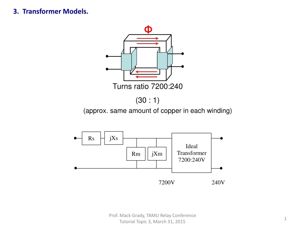
3. Transformer Models. Φ. jXs. Rs. Ideal. Transformer. jXm. Rm. 7200:240V. Turns ratio 7200:240. (approx. same amount of copper in each winding). (30 : 1). 7200V 240V. 3. Transformer Models, cont. Open Circuit Test. Ioc. jXs. Rs. +. Ideal. Transformer.

E N D
3. Transformer Models. Φ jXs Rs Ideal Transformer jXm Rm 7200:240V Turns ratio 7200:240 • (approx. same amount of copper in each winding) (30 : 1) 7200V 240V Prof. Mack Grady, TAMU Relay Conference Tutorial Topic 3, March 31, 2015
3. Transformer Models, cont. Open Circuit Test Ioc jXs Rs + Ideal Transformer Voc jXm Rm 7200:240V - 7200V 240V Φ Open circuit test: Open circuit the 7200V - side, and apply 240V to the 240V - side. The winding currents are small, so the series terms are negligible. ~ V oc = || R jX ~ Turns ratio 7200:240 m m I oc Prof. Mack Grady, TAMU Relay Conference Tutorial, Topic 3, March 31, 2015
Isc + Vsc - Short circuit test: Short circuit the 240V-side, and raise the 7200V-side voltage to a few percent of 7200, until rated current flows. There is almost no core flux so the magnetizing terms are negligible. Φ Turns ratio 7200:240 3. Transformer Models, cont. Short Circuit Test jXs Rs Ideal Transformer jXm Rm 7200:240V 7200V 240V Prof. Mack Grady, TAMU Relay Conference Tutorial, Topic 3, March 31, 2015
X / R Ratios for Three - Phase Transformers • 345kV to 138kV, X/R = 10 • Substation transformers (e.g., 138kV to 25kV or 12.5kV, X/R = 2, X = 12% • 25kV or 12.5kV to 480V, X/R = 1, X = 5% • 480V class, X/R = 0.1, X = 1.5% to 4.5% jXs Rs Ideal Transformer jXm Rm 3. Transformer Models, cont. Prof. Mack Grady, TAMU Relay Conference Tutorial, Topic 3, March 31, 2015
jXs Rs Ideal Transformer jXm Rm 7200:240V 7200V 240V 3. Transformer Models, cont. • 1. Given the standard percentage values below for a 125kVA transformer, determine the R’s and X’s in the diagram, in Ω. • If the R’s and X’s are moved to the 240V side, compute the new Ω values. • If standard open circuit and short circuit tests are performed on this transformer, what will be the P’s and Q’s (Watts and VArs) measured in those tests? Load loss Single Phase Transformer. Percent values on transformer base. Winding 1 kV = 7.2, kVA = 125 Winding 2 kV = 0.24, kVA = 125 %Imag= 0.5 %Load loss = 0.9 %No-load loss = 0.2 %Xs = 2.2 Xs No-load loss Magnetizing current Prof. Mack Grady, TAMU Relay Conference Tutorial, Topic 3, March 31, 2015
Secondary Lines 21% Transformer No- Load Annual Feeder Loss Components 45% Primary Lines 26% TransformerLoad 8% 3. Transformer Models, cont. EPRI Study, Distribution Feeder Loss Example Annual energy loss = 2.40% • Largest component is transformer no-load • loss (45% of the 2.40%) • Modern Distribution Transformer: • Load loss at rated load (I2R in conductors) = 0.75% of rated transformer kW. • No load loss at rated voltage (magnetizing, core steel) = 0.2% of rated transformer kW. • Magnetizing current = 0.5% of rated transformer amperes
Wye-Equivalent One-Line Model jXs Rs Ideal N1:N2 Transformer jXm Rm N1 : N2 N1:N2 N1:N2 Y - Y 3. Transformer Models, cont. A three-phase transformer can be three separate single-phase transformers, or one large transformer with three sets of windings A N Reflect to side 2 using individual transformer • turns ratio N1:N2 , GY-GY Standard 345/138kV autotransformers, • Δ have a tertiary 12.5kV winding to permit harmonic current rd circulating 3 Prof. Mack Grady, TAMU Relay Conference Tutorial, Topic 3, March 31, 2015
3. Transformer Models, cont. For Modeling a Delta-Delta Connection, Convert the Transformer to Equivalent Wye-Wye Wye-Equivalent One-Line Model jXs Rs A Ideal 3 3 Transformer N1:N2 Rm jXm 1 2 N N 3 3 : 3 3 N Convert side 1 impedances from delta to • N1:N2 equivalent wye Then reflect to side 2 using individual • transformer turns ratio N1:N2 N1:N2 - • Δ • Δ Prof. Mack Grady, TAMU Relay Conference Tutorial, Topic 3, March 31, 2015
Rs jXs A Ideal 3 3 Transformer N1:N2 Rm jXm 1 N 3 3 : 2 N 3 N N1:N2 • Convert side 1 impedances from delta to wye • Then reflect to side 2 using three-phase line-to-lineturns ratio • Has 30° degree phase shift due to line-to-neutral to line-to-line relationship. ANSI standard requires the transformer to be labeled such that high-voltage side leads the low-voltage side by 30° . N1:N2 • Δ - Y 3. Transformer Models, cont. For Modeling a Delta-Wye Connection, Convert the Transformer to Equivalent Wye-Wye Wye-Equivalent One-Line Model Prof. Mack Grady, TAMU Relay Conference Tutorial, Topic 3, March 31, 2015
jXs Ideal N1:N2 Transformer 2 N 1 : N 3 • Reflect to side 2 using three-phase bank line-to-line turns ratio • Has 30° degree phase shift due to line-to-neutral to line-to-line relationship. ANSI standard requires the transformer to be labeled such that high-voltage side leads the low-voltage side by 30° N1:N2 N1:N2 Y - • Δ 3. Transformer Models, cont. For Modeling a Wye-Delta Connection, Convert the Transformer to Equivalent Wye-Wye Wye-Equivalent One-Line Model Rs A jXm Rm N Thus, for all configurations, equivalent wye-wye transformer ohms can be reflected from one side to the other using the three-phase bank line-to-line turns ratio Prof. Mack Grady, TAMU Relay Conference Tutorial, Topic 3, March 31, 2015