Download
1 / 15
340 likes | 780 Vues
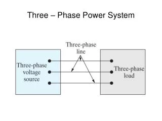
Power System Restoration (Black Start). Black Start Panel Session IEEE PES Summer Meeting Chicago, Illinois July 23, 2002 M. M. Adibi IRD Corp., P.O. Box 34901 Bethesda, MD 20827 madibird@aol.com. Pre-disturbance Conditions. Peak load, low voltage, large network loads

E N D
Power System Restoration(Black Start) Black Start Panel Session IEEE PES Summer Meeting Chicago, Illinois July 23, 2002 M. M. Adibi IRD Corp., P.O. Box 34901 Bethesda, MD 20827 madibird@aol.com (c) IRD 2002
Pre-disturbance Conditions Peak load, low voltage, large network loads Light load, high voltage, no cycling units Long weekends (Labor Day) Scheduled maintenance (c) IRD 2002
Post-disturbance Status Complete collapse with no interconnection assistance Partial collapse with interconnection assistance Power system beak-up (System Islands) (c) IRD 2002
The Three Restoration Stages Preparation stage, actions are time critical (1-2 hours) System integration, achieving post-restoration target system (3-4 hours) Load restoration, minimizing MWH (8-10 hours) (c) IRD 2002
Initial Sources of Power Combustion Turbines, Start-up in 5-15 min., probability of success 30 –50%, limited under-excitation, use low voltage links Run-of-the-River Hydro, Pumped- Storage, Start-up 5-10 min., probability of success is high, can use HV links (c) IRD 2002
Once-through Units with full-load rejection, probability of success 20-80%, maximum elapsed time to min. loading 30 minutes, coordinated loading problem to min. gen. Low Frequency Isolation Scheme (LFIS) and Controlled Islanding, probability of success is low. Initial Sources of Power(cont.) (c) IRD 2002
Initial Critical Loads Cranking drum-type units, high priority Pipe-type cable pumping plants, high priority Transmission and distribution stations, hightomedium priority depending on locations Industrial load, medium to low priority (c) IRD 2002
Black Start Steam Electric Units(Drum Type Boilers) Are base load units, supply large portions of demand Max. elapsed time for hot re-start is 30-45 minutes Min. elapsed time for cold start-up is 3-4 hours Are remote from the load centers Need cranking power 5-7% of their ratings Min. generation 25 to 30 % (c) IRD 2002
One-Line diagram of a SE Unit System Bus (345 kV) GSU Taps (5 no-load) GSU XFMR Generator Bus (18.0 kV) AUX Taps (5 no-load) Standby Taps (5 on-load) SE Gen. AUX XFMR Standby XFMR Generator: Max 185 MW Min 90 MW Normally Open AUX Load Bus (4.16 V) AUX Load Bus (4.16 kV) Large Induction Motors (350 to 6000 Horse Power) (c) IRD 2002
Combustion Turbine Units (cranking source) Are peaking units, supply daily peak load Cold start up within 5 – 10 minutes Possibility of successful start up is 1 in 3 Are close to the load centers Need small local cranking for start ups Hot restart within 2 – 3 hours (c) IRD 2002
One-Line diagram of the CT Unit System Bus (115 kV) GSU Taps (6 no-load) GSU XFMR Generator Bus (13.8 kV) AUX Taps (5 no-load) CT Gen AUX XFMR Local XFMR Twin Generators (42 MVA, 85% PF) XFMR Taps (5 on-load) AUX Load Bus (480 V) Local Load Bus (34.5 kV) AUX Load (150 kW) Local Load (7.5 MW) (c) IRD 2002
A Typical Black Start System (c) IRD 2002
Cumulative Starting & Running Auxiliaries (c) IRD 2002
Conclusions Characteristics of steam units dictate parallel start ups (45 to 60 minutes) SE units should be individually matched with black start CT units Systems are sectionalized into subsystems, each at least having one SES & one CTS Cranking operation uses generation, transmission and distribution facilities (c) IRD 2002
Recommendations CT units should be able to absorb line & cable charging currents CT units should be able to supply reactive power required for the start ups of large induction motors Each black start operation should be planned, analyzed/simulated, field tested and then operators trained and exercised in its implementations (c) IRD 2002