Download
1 / 1
10 likes | 123 Vues
CLIC recombination scheme for the low energy operation mode . A. Gerbershagen, D. Schulte, CERN, Geneva, Switzerland P. N. Burrows, John Adams Institute, Oxford University, Oxford, UK. Recombination Scheme

E N D
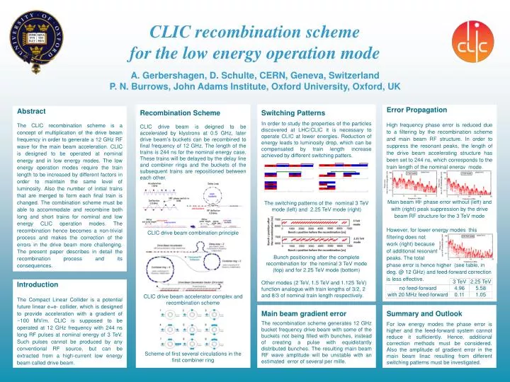
CLIC recombination scheme for the low energy operation mode A. Gerbershagen, D. Schulte, CERN, Geneva, SwitzerlandP. N. Burrows, John Adams Institute, Oxford University, Oxford, UK Recombination Scheme CLIC drive beam is deigned to be accelerated by klystrons at 0.5 GHz, later drive beam’s buckets can be recombined to final frequency of 12 GHz. The length of the trains is 244 ns for the nominal energy case. These trains will be delayed by the delay line and combiner rings and the buckets of the subsequent trains are repositioned between each other. CLIC drive beam combination principle CLIC drive beam accelerator complex and recombination scheme Scheme of first several circulations in the first combiner ring Switching Patterns In order to study the properties of the particles discovered at LHC/CLIC it is necessary to operate CLIC at lower energies. Reduction of energy leads to luminosity drop, which can be compensated by train length increase achieved by different switching patters. The switching patterns of the nominal 3 TeV mode (left) and 2.25 TeV mode (right) Bunch positioning after the complete recombination for the nominal 3 TeV mode (top) and for 2.25 TeV mode (bottom) Other modes (2 TeV, 1.5 TeV and 1.125 TeV) function analogue with train lengths of 3/2, 2 and 8/3 of nominal train length respectively. Error Propagation High frequency phase error is reduced due to a filtering by the recombination scheme and main beam RF structure. In order to suppress the resonant peaks, the length of the drive beam accelerating structure has been set to 244 ns, which corresponds to the train length of the nominal energy mode. Main beam RF phase error without (left) and with (right) peak suppression by the drive beam RF structure forthe 3 TeV mode However, for lower energy modes this filtering does not work (right) because of additional resonantpeaks. The total phase error is hence higher (see table, in deg. @ 12 GHz) and feed-forward correction is less effective. Abstract The CLIC recombination scheme is a concept of multiplication of the drive beam frequency in order to generate a 12 GHz RF wave for the main beam acceleration. CLIC is designed to be operated at nominal energy and in low energy modes. The low energy operation modes require the train length to be increased by different factors in order to maintain the same level of luminosity. Also the number of initial trains that are merged to form each final train is changed. The combination scheme must be able to accommodate and recombine both long and short trains for nominal and low energy CLIC operation modes. The recombination hence becomes a non-trivial process and makes the correction of the errors in the drive beam more challenging. The present paper describes in detail the recombination process and its consequences. Introduction The Compact Linear Collider is a potential future linear e+e- collider, which is designed to provide acceleration with a gradient of ~100 MV/m. CLIC is supposed to be operated at 12 GHz frequency with 244 ns long RF pulses at nominal energy of 3 TeV. Such pulses cannot be produced by any conventional RF source, but can be extracted from a high-current low energy beam called drive beam. Main beam gradient error The recombination scheme generates 12 GHz bucket frequency drive beam with some of the buckets not being filled with bunches, instead of creating a pulse with equidistantly distributed bunches. The resulting main beam RF wave amplitude will be unstable with an estimated error of several per mille. Summary and Outlook For low energy modes the phase error is higher and the feed-forward system cannot reduce it sufficiently. Hence, additional correction methods must be considered. Also the amplitude of gradient error in the main beam linacresulting from different switching patterns must be investigated.