Download
1 / 91

E N D
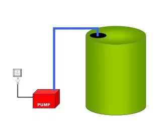
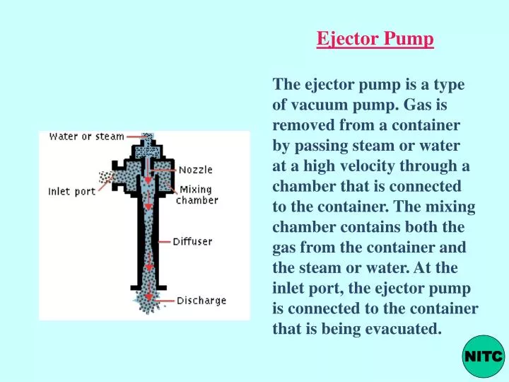
Ejector Pump The ejector pump is a type of vacuum pump. Gas is removed from a container by passing steam or water at a high velocity through a chamber that is connected to the container. The mixing chamber contains both the gas from the container and the steam or water. At the inlet port, the ejector pump is connected to the container that is being evacuated. NITC
Melting NITC
For both ferrous and non ferrous castings.(melting temperature upto 16500C) • Very accurate details obtained in intricate shapes • Excellent surface finish, machining and cleaning costs minimum. • Accuracy of 0.002 mm per mm obtained. • But, casting process costly. • Casting cost high. NITC
PRODUCTION OF ALLOY WHEELS METHOD OF PRODUCTION; COUNTER PRESSURE DIE CASTING The manufacturing process commences with the smelting of pure aluminium ingots in a 5-ton basin type furnace. NITC
The furnace is a dry sole type furnace whose function is to smelt the primary raw material, and reprocess alloy scraps consisting of:- wheels used in destructive testing by the quality control department, and the risers and gates removed from the wheels following the casting process. From the dry sole furnace, the molten aluminium is transferred to the alloy induction furnaces via a feed channel to enable the mixing and smelting of the elements required in the preparation of the alloy – AlSi 7. NITC
A spectrometer equipped quality control laboratory is used during the process of alloy preparation to ensure the composition of the alloy meets the required specification during this stage of the preparation process. Spectrometer analysis sampling is also applied randomly to finished wheels. NITC
Molten alloy is transferred to holding furnaces for eventual transfer to the casting machines. After the molten alloy has been tested for conformance to specifications, it is transported to the alloy treatment station where the alloy is submitted to three procedures performed by an automatic process control system. The treatment unit introduces salts into the molten alloy using a high-speed spinner, where the alloy purification is assisted by the use of nitrogen gas jets. The three procedures to which the molten alloy is submitted are:- ·Degassing ·Refining ·Modifying NITC
These processes are intrinsic to the removal of all undesirable impurities in the molten alloy. The automation of these processes improves the product quality control, production rates and importantly minimizes wastage by reducing the possibilities of rejection of the finished product. Following the procedures to ensure that the molten alloy conforms to precise specification, it is transported in holding furnaces to the low pressure casting machines. These furnaces are designed to produce casting by employing pressurised air within a range of 0.3 – 1.0 atm., the pressurization being monitored and varied by a computerized process control system according to flow requirements NITC
Computerized process technology automatically controls the casting process, and then, at the end of the 4.5 minute casting cycle, cools and ejects the wheel onto a catcher arm designed for this purpose. Holding furnaces contain between 500-750kg of molten alloy - sufficient for up to approx. 4 hours of casting operations. When the holding furnace is exhausted it is exchanged for a full replacement furnace using the transfer shuttle - illustrated above - without interruption to the casting process. Hydraulic systems control many of the unit’s operating movements, and, due to high operating temperatures many measures have to be taken to enable minimization of risk and reduction of maintenance of these systems. For example, it is necessary for all hydraulic systems to employ fire resistant fluids thereby eliminating fire risk. Likewise, all hydraulic hoses have to be metal covered and insulated against accidental splashes of molten metal. NITC
The operators of the Counter Pressure Casting Machines perform an initial visual quality control as the wheels are ejected from each unit and palleted ready for transport to the Riser cutting department. At this first stage in the machining process following casting, the removal of the gates and risers is carried out by automated machines designed for this purpose – with a cycle time of 50 seconds per wheel. The CNC riser-cutting unit performs the following operations NITC
· Pre-boring of the central hole of the wheel · Removal of the channel burrs corresponding to the surface joints on the Die’s moving parts · Trimming upper and lower edges of the wheel The working cycle of the Riser cutting unit is completely automated to improve both quality control and production rate per machine. All waste products are collected for recycling at the foundry. The machine operations are performed under a suction hood to remove aluminium dust and particulates from the environment in proximity to this unit. Customarily, after the machining processes have been completed on the newly cast wheels, the wheels are passed to the quality control unit for examination under a variety of non-destructive and destructive tests. Batch sampling of the wheels may involve taking a 1-2mm scrape taken using a lathe, and running a spectrometer analysis of the resulting alloy sample. NITC
X-Ray analysis machine in Quality control department Non-destructive testing is undertaken using radiography processes. It is common practice for the VM customers to include within their contractual requirements testing volumes and timescales (i.e. before or after machining). The X-ray control equipment can be pre-set with information from up to 1000 wheel designs, and wheels can be inspected on a wide variety of positions / angles (normally 20 position variants). The wheel manipulator for handling the wheels during the inspection cycle has 5 fully computerized axes and a roller conveyor automatically provides loading/unloading of the machine with the wheels for inspection. The X-Ray unit takes 2 wheels at a time - one in process of inspection cycle, and a second wheel in a ‘holding’ position. As the testing machine completes the automated inspection cycle, it simultaneously ejects the inspected wheel, puts the second wheel into position for inspection and draws another wheel into the ‘holding’ position. Thus the performance inspection cycle is enhanced to its maximum possibility. During an inspection, the operator monitors the x-ray image on a viewing console and has the possibility of magnifying the image or ‘replaying’ the process to precisely identify any casting defect exposed by this machine. NITC
The next stage of the quality control process is undertaken on Geometrical control benches where the physical dimensions of the wheels are compared with the specification standard using pantographs and micrometers. The semi- finished product, having been submitted to various machining and quality control procedures are passed to the finishing dept. which - dependent upon client specification - either submits the wheels through an automated paint shop - or polishing line where a bright lacquer finish has been specified. The finished wheels are then palleted and wrapped in polyethylene film - ready for transfer to a wheel/tyre assembly plant - prior to final shipment to the production lines of the VM customer NITC
The pallet/box wrapping equipment consists of a motorized wrapping machine – allowing pallets to beplaced on a rotating turntable, and providing film wrapping through this rotation with a fixed unit holding the polyethylene roll. The finished wheels are stored on pallets/boxes until shipping. COUNTER PRESSURE DIE CASTING MACHINES The casting machines have evolved over 25 years of development and manufacturing experience of counter-pressure & low pressure casting machines. Simplicity of design, operating convenience and ease of maintenance are the core attributes that produce highest levels of egonomics and safety. The above principles are well emphasised by the rugged vertical tie-bar construction incorporating an integral holding furnace. The well tried and proven technical solutions provide stability, accuracy in guiding and controlling the precision of the moving parts, and include essential rigidity, operational dependability and longevity of the machines. All machines are designed to withstand heavy-duty service in foundries operating continuous 24 hour cycles. NITC
INSPECTION OF CASTINGS • SEVERAL METHODS • VISUAL • OPTICAL • - FOR SURFACE DEFECTS • SUBSURFACE AND INTERNAL DEFECTS THROUGH NDTs & DTs • PRESSURE TIGHTNESS OF VALVES BY SEALING THE OPENING AND PRESSURISING WITH WATER NITC
SURFACE METALLIC PROJECTION (4) DEFECTIVE SURFACE (11) CHANGE IN DIMENSION- WARP INCOMPLETE CASTING MISRUN, RUNOUT CAVITY- BLOWHOLES, SHRINKAGE PINHOLES DISCONTINUITY HOT CRACK COLD SHUT, COLD CRACK SUBSURFACE SUBSURFACE CAVITY INCLUSIONS DISCONTINUITY CASTING DEFECTS NITC
NDTs Methods of testing Destructive- Non destructive- Radiagraphic Ultrasonic NITC
Non Destructive Testing with Ultrasonics for flaw Detection in Castings, Weldments, Rails, Forged Components etc. NITC
ULTRASONIC TESTING NITC
Why Ultrasonics ? ……… Flaw detection in metals and nonmetals Flaw measurement in very thick materials Internal and surface flaws can be detected Inspection costs are relatively low. Rapid testing capabilities and portability. NITC
Ultrasonic waves are simply vibrational waves having a frequency higher than the hearing range of the normal human ear, which is typically considered to be 20,000 cycles per second (Hz). The upper end of the range is not well defined. Frequencies higher than 10 GHz have been generated. However, most practical ultrasonic flaw detection is accomplished with frequencies from 200 kHz to 20 MHz, with 50 MHz used in material property investigations. Ultrasonic energy can be used in materials and structures for flaw detection and material property determinations. NITC
Ultrasonic waves are mechanical waves (in contrast to, for example, light or x-rays, which are electromagnetic waves) that consist of oscillations or vibrations of the atomic or molecular particles of a substance about the equilibrium positions of these particles. Ultrasonic waves behave essentially the same as audible sound waves. They can propagate in an elastic medium, which can be solid, liquid, or gaseous, but not in a vacuum. NITC
In solids, the particles can (a) oscillate along the direction of sound propagation as longitudinal waves, or (b) the oscillations can be perpendicular to the direction of sound waves as transverse waves. At surfaces and interfaces, various types of elliptical or complex vibrations of the particles occur. NITC
THEORYOF TESTING NITC
MACHINE SPECIFICATIONS Make: Weight: Calibration range upto 9999 mm. Choice of Frequency range Provision for adjusting gain. Documentation possibility via printer Limitation:……………. NITC
Probe NITC
SCANNING TECHNIQUES • Pulse Echo method • Straight beam method • Angle beam method NITC
PULSE ECHO METHOD NITC
Inspection of: • Gas porosity • Slag Entrapment • Cracks NITC
With the exception of single gas pores all the defects listed are usually well detectable by ultrasonics. Ultrasonic flaw detection has long been the preferred method for nondestructive testing , mainly in welding applications. This safe, accurate and simple technique has pushed ultrasonics to the forefront of inspection technology. NITC
The proper scanning area for the weld: First calculate the location of the sound beam in the test material. Using the refracted angle, beam index point and material thickness, the V-path and skip distance of the sound beam is found. Then identify the transducer locations on the surface of the material corresponding to the crown, sidewall, and root of the weld. NITC
Inspection of Rails NITC
New trend: Ultrasonic Simulation - UTSIM UTSIM is a user interface integrating a CAD model representing a part under inspection and an ultrasound beam model. NITC
Ultrasonic sizing of small flaws with the distance-amplitude-correction (dac) curve NITC
Casting Defects • Metal casters try to produce perfect castings. • A few castings, however, are completely free of defects. • Modern foundries have sophisticated inspection equipment which can detect small differences in size and a wide variety of external and even internal defects. For example, slight shrinkage on the back of a decorative wall plaque is acceptable whereas similar shrinkage on a position cannot be tolerated. • No matter what the intended use, however, the goal of modern foundries is zero defects in all castings
Scrap castings cause much concern. • In industry, scrap results in smaller profits for the company and ultimately affects individual wages. • Scrap meetings are held daily. Managers of all the major departments attend these meetings. They gather castings that have been identified as scrap by inspector. The defect is circled with chalk. An effort is made to analyze the cause of the defect, and the manager whose department was responsible for it is directed to take corrective action to eliminate that specific defect in future castings. • There are so many variables in the production of a metal casting that the cause is often a combination of several factors rather than a single one. • All pertinent data related to the production of the casting (sand and core properties, pouring temperature) must be known in order to identify the defect correctly. • After the defect is identified attempt should be to eliminate the defect by taking appropriate corrective action.
SURFACE METALLIC PROJECTION – Swell, Crush, Mould Drop, Fillet Vein DEFECTIVE SURFACE – Erosion Scab, Fusion, Expansion Scab, Rat tails, Buckle, Seams, Gas Runs, Fillet Scab, Rough Surface, Slag Inclusion, Elephant Skin CHANGE IN DIMENSION- Warped casting INCOMPLETE CASTING- Misrun, Run out CAVITY- Blow Holes, Shrinkage cavity, Pinholes DISCONTINUITY- Hot6 Cracking, Cold Shut, Cold Cracking SUBSURFACE SUBSURFACE CAVITY- Blow Holes, Pin Holes, Shrinkage Porosity, Internal Shrinkage, Severe Roughness INCLUSIONS- Gas Inclusions, Slag, Blow Holes DISCONTINUITY- Cold Shuts CASTING DEFECTS NITC
FINS OR FLASH ON CASTINGS -AsMetallic Projections • Joint flash or fins. Flat projection of irregular thickness, often with lacy edges, perpendicular to one of the faces of the casting. It occurs along the joint or parting line of the mold, at a core print, or wherever two elements of the mold intersect. • Possible Causes • Clearance between two elements of the mold or between mold and core; • Poorly fit mold joint. • Remedies • Care in pattern making, molding and core making; • Control of their dimensions; • Care in core setting and mold assembly; • Sealing of joints where possible.
Flask was disturbed while investment was setting. • Base was removed too soon. • Flask was allowed to partially dry before dewaxing. • Incorrect dewaxing or a furnace malfunction. • Flask burned out and allowed to cool below (500oF (260oC) before casting reheating, flask allowed to cool between dewax and placement in preheated oven. • Flask was improperly handled or dropped. • Speed was set too high on centrifugal casting machine. • Patterns were placed on one plane. The should be staggered on top rack. • Incorrect water powder ratio was used. • Not enough investment was placed over the patterns. • Flask was placed too close to heat source in burnout oven. • Flasks were not held at low burnout temperature long enough.
DEFECTS IN CASTINGS- CAN BE ELIMINATED/MINIMISED BY PROPER DESIGN, MOLD PREPARATION, PROPER POURING. NITC