Download

1 / 45
450 likes | 567 Vues
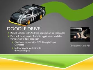
Team 6. Doodle Drive. |. |. |. Peachanok Lertkajornkitti. Alexander Curtis. Jun Pan. Edward Kidarsa. Outline. Project overview Project-specific success criteria Block diagram Component selection rationale Packaging design Schematic and theory of operation PCB layout

E N D
Team 6 Doodle Drive | | | PeachanokLertkajornkitti AlexanderCurtis JunPan EdwardKidarsa
Outline • Project overview • Project-specific success criteria • Block diagram • Component selection rationale • Packaging design • Schematic and theory of operation • PCB layout • Software design/development status • Project completion timeline • Questions / discussion
Project Overview • Android application as controller • Robot vehicle with microcontroller • Path will be drawn in Android application and the vehicle will follow that path • Outdoor mode with GPS, Google Maps, Compass • Indoor mode with tilt control
Project-specific success criteria • 1. An ability to send and receive encoded data to an Android Device via Bluetooth • 2. An ability to make a turn without stopping • 3. An ability to navigate to a designated GPS coordinate with some approximation (GPS uncertainty of about ~5m) • 4. An ability to monitor the battery power level • 5.An ability to detect obstacles 0.5m away in a ~120 degree field of vision and alert user (vibrate)
Block Diagram PWM
Component selection rationale • MICROCONTROLLER • BLUETOOTH • POSITIONING: • GPS • COMPASS • POWER: • FUEL GAUGE • BATTERY RE-CHARGE CHIP
MICROCONTROLLER RATIONALE • NXP LPC1768 • mBedprototyping environment and compiler • Quick and efficient prototyping with mbed SDK • Ease of use • Good amount of sample code/libraries exist • Enough ports for necessary peripherals • 3x UART, 2x I2C, 6x PWM channels • Input capture pins with timer
POSITIONING/Communication Components RATIONALE • GPS: UP-501 • Most cost effective according to comparison study (Sparkfun) • Low power consumption ~80mW • Configurable update rate (up to 10 Hz) • High accuracy ~2.5m • BLUETOOTH: RN-41 • Class 1 device (range up to 100m as opposed to Class 2, 10m) • LEDs indicating the status of the connection • Compass: LSM303DLM • Cheapest 3-axis compass with tilt compensation
POWER components RATIONALE • FUEL GAUGE: LTC4150 • Compatible with six NiMH cell configuration • Low feature and simple interfacing • Interrupt counting or input capture • BATTERY RE-CHARGE CHIP: • Compatible with six NiMH cell configuration • Switch mode charging for high efficiency and low heat dissipation • Accurate charge termination (dT/dt method)for safety
PACKAGING DESIGN • Durable rugged body and wheels • Large enough to fit components on the PCB • Mounted PCB • Portable • Minimal mechanical components
MicroController 1: Compass (I2C) 2: Bluetooth (UART) 3: GPS (UART) 4: H-Bridge (PWM, GPIO) 5: Ultrasonic (GPIO) 6: Optical Encoders (Input Capture, GPIO) 7: Crystal Oscillator 8: Fuel Gauge (GPIO) 9: Servo (PWM) 5 6 4 9 3 8 7 1 2
PCB LAYOUT: DESIGN CONSIDERATIONS • GPS far away from everything • Especially active circuits such as regulators • Bluetooth away from power supply • No traces / ground plane / vias allowed under antenna • Antenna end protrude 5mm beyond any enclosure • Traces • 0.016 in used for most traces • Power and Ground traces used 0.040 when possible, some pins were too small • Routing • 45 degrees routings were used as much as possible • T intersections were used to avoid acute angles
PCB LAYOUT: Micro • Center of PCB to be accessible to everything else • Headers on all sides for access to pins ( debugging etc ) • Bypass capacitors placed next to micro before headers • External oscillator used • Located near the microcontroller after header • Routing • GPS and H-Bridge was on either ends of the board, thus had long connecting traces • Traces • Due to the small size of the pins, only 0.01 in traces were able to be used • JTAG header is connected to Micro
PCB LAYOUT: POwer • Power Circuit: • 2 Motors, H-Bridge, Battery Recharge Circuit, 2 Voltage Regulators • Power circuit located near edge of PCB away from transmission peripherals • Placed near each other • Power circuits may have current feedback / current spikes need wider traces than the rest of the circuit
PCB LAYOUT: VOLTAGE REGULATORS + FUEL GAUGE
PCB LAYOUT: VOLTAGE REGULATORS + FUEL GAUGE
PCB LAYOUT: CHARGING CHIP PIN HEADERTO BATTERY
PCB LAYOUT: CHARGING CHIP PIN HEADERTO BATTERY
PCB LAYOUT: Compass + Servo + JTAG + ULTRASONIC SENSOR+ OPTICAL ENCODER + OSCILLATOR JTAG PROGRAMMING PINS
PCB LAYOUT: Compass + Servo + JTAG + ULTRASONIC SENSOR+ OPTICAL ENCODER + OSCILLATOR JTAG PROGRAMMING PINS
Software Preliminary Design • Microcontroller • Done testing: • Ultrasonic sensors, H Bridge, Servo, Bluetooth • Need to test: • Compass (I2C) • GPS (UART) • Fuel Gauge (I/O)
Software Preliminary Design • Android application • Google Maps API • Battery status bar • Toggle switch between Indoor/Outdoor modes • Progress: • Android output angles when tilting (for Indoor Mode) • Google Maps displays on screen with ability to draw lines/polygons on screen • Battery status bar • Bluetooth interface
THANK YOU! Questions / Discussions