Download
1 / 10
100 likes | 248 Vues
Full Wave Modeling of Body Area Path Loss and Related Antenna Modeling. S. Makarov & G. Noetscher Ant. Lab ECE Dept., WPI, MA. Task #1. Compare performance of in-house MATLAB FDTD and FEM simulator Ansoft/ANSYS HFSS

E N D
Full Wave Modeling of Body Area Path Lossand Related Antenna Modeling S. Makarov & G. Noetscher Ant. Lab ECE Dept., WPI, MA
Task #1 • Compare performance of in-house MATLAB FDTD and FEM simulator Ansoft/ANSYS HFSS • Establish how important the effect of internal body composition is on the performance of out-of-body wireless link • Establish how important the effect of body shape variation is on the performance of out-of-body wireless link
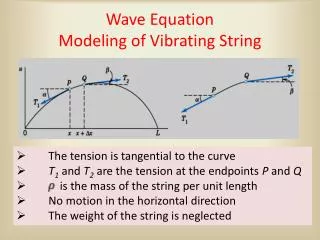
Typical Simulation Results Case 04_05: Antenna position: X = 156.5mm, Z = -390.5mm.
Conclusions: out-of-body networks at 402 MHz • Performed code-to-code validation • Established that FDTD is superior to FEM w.r.t. CPU time • Established that: • Out-of-body wireless link weakly depends on internal body composition • Out-of-body wireless link weakly depends on body shape • Critical diffraction parameters include path length and body area projected onto a plane perpendicular to path
Task #2-In-body to on-body link 1x8 dipole array Homogeneous body Near-field scanning array task: ~2λ x 2λ x 2λ domain
Task#3-In-body Antenna Design Independent of ras long as r >200 Induced voltage is found using Faraday’s law (reff >~10-20)
Antenna matching and tuning Series matching for low input impedance Input impedance is on the order of several ohms (loss resistance)
Antenna challenges + = Small impedance bandwidth: R/(2L) High loss and low efficiency A 3D coil antenna is a must Direct measurements are difficult to perform Suggested: signal strength measurements with passive RFID SAW sensors and the calibrated reader antenna