Download
1 / 17
260 likes | 1.14k Vues
PSCAD Simulation of Grid Tied Photovoltaic and Wind Farms. By Abdulrahman Kalbat. PSCAD/EMTDC. PSCAD : Power Systems Computer Aided Design PSCAD is Graphical User Interface for EMTDC simulation engine EMTDC : Electromagnetic Transients including DC

E N D
PSCAD Simulation of Grid Tied Photovoltaic and Wind Farms By AbdulrahmanKalbat
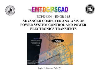
PSCAD/EMTDC • PSCAD: Power Systems Computer Aided Design • PSCAD is Graphical User Interface for EMTDC simulation engine • EMTDC: Electromagnetic Transients including DC • Simulate time domain instantaneous response of the power systems www.pscad.com
PSCAD Vs. Simulink • PSCAD’s interface is specialized for power system networks • Faster time domain simulation speed • Matlab/Simulink Interface in PSCAD • Availability of the models for Solar Panels and Wind Turbines Venayagamoorthy, Ganesh K., “Comparison of power system simulation studies on different platforms – RSCAD, PSCAD/EMTDC, and SIMULINK SimPowerSystems,” International Conference on Power System Operations and Planning, 2005
Power Network Under Study • Complete Utility Grid (from generation to distribution) • Utility Scale PV System • Utility Scale Wind Turbine System
Previous Research Done • Electrical model development and validation for distributed resources for NREL [1] • Modeling of a photovoltaic system with a distributed energy storage system [2] • Power quality effects of high PV penetration on Distribution Networks [3] [1] M.G. Simões, B. Palle, S. Chakraborty, and C. Uriarte, “Electrical Model Development and Validation for Distributed Resources ,” NREL, Golden, CO, 2007 [2} Anthony W. Ma, “MODELING AND ANALYSIS OF A PHOTOVOLTAIC SYSTEM WITH A DISTRIBUTED ENERGY STORAGE SYSTEM,” M.S. Thesis, Dept. Elect. Eng., California Polytechnic State Univ., San Luis Obispo, CA, 2012 [3] Minas Patsalides, et. al., “Towards the establishment of maximum PV generation limits due to power quality constraints,” Electrical Power and Energy Systems,
Expected Results • Effects of PV and Wind systems on the power quality of the utility grid • Frequency • Voltage • System’s response to faults: • Line to line faults • Line to ground faults • Lightning strikes
Solar Photovoltaic Model • Photovoltaic Model • Directly convert solar energy into electricity • Maximum Power Point Tracker Model • Ensure optimum output at varying temperature and insolation • Regulate and step-down the high voltage of the PV array. Models developed by: AthulaRajapakse, Dept. of Electrical and Computer Engineering, Univ. of Manitoba, Winnipeg, Canada
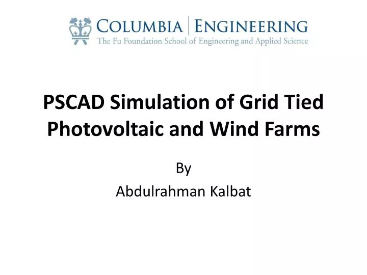
Grid Connected PV Solar Radiation + Cell Temperature Data PV Array + Output Capacitor DC-DC Converter for MPP Tracking DC-bus Capacitor and Start-up Charging 3-phase Inverter Bridge Anthony W. Ma, “MODELING AND ANALYSIS OF A PHOTOVOLTAIC SYSTEM WITH A DISTRIBUTED ENERGY STORAGE SYSTEM ,” M.S. Thesis, Dept. Elect. Eng., California Polytechnic State Univ., San Luis Obispo, CA, 2012
Maximum Power Point Tracker Variable Solar Radiation Increase Solar Radiation Increase Short Circuit Current
Maximum Power Point Tracker Variable Temperature Increase Temperature Decrease Open Circuit Voltage
Maximum Power Point Tracker Maximum Power Yield
Maximum Power Point Tracker Regulate and step-down the high voltage of the PV array.
3-Phase Inverter Output Current Output Voltage
Wind Turbine Model • Inputs • Vw: Wind speed (must be a positive value) [m/s] • W: Machine mechanical speed [rad/s] • Beta: Pitch angle [°] • Outputs • Tm: Output torque of the turbine [p.u.] • P: Output power of the turbine [p.u.] • Inputs • Wm: Mechanical speed of the machine [rad/s] • Pg: Power output of the machine based on the machine rating [p.u.] • Output • Beta: Pitch angle [°]