Download
1 / 7
70 likes | 205 Vues
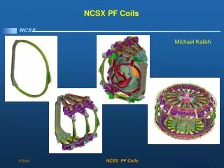
Metrology for NCSX. Steve Raftopoulos and the NCSX Metrology Team. Metrology Systems. Hardware: Two laser trackers: Leica LTD 500 (Interferometer and ADM unit) upgraded to EmScon interface Faro Tracker X (ADM unit only) Three Romer articulating arms – 12 ft length. Software:

E N D
Metrology for NCSX Steve Raftopoulos and the NCSX Metrology Team
Metrology Systems • Hardware: • Two laser trackers: • Leica LTD 500 (Interferometer and ADM unit) upgraded to EmScon interface • Faro Tracker X (ADM unit only) • Three Romer articulating arms – 12 ft length. • Software: • Verisurf CAD-based 3D inspection software running on all hardware platforms. Metrology software built on top of MasterCam CAD?CAM software. Allows manipulation of CAD data and creation of layers for organization of metrology data. • Leica AXYZ and EmScon software available for interfacing and Diagnostics for Leica Laser Tracker. • Faro Utilities software for interfacing with Faro Laser Tracker
Coil winding and Initial Coordinate System Determination. • Coordinate system of coil is established during coil winding phase with the coil in a vertical position in the ring. • Approximately 10,000 measurement points (taken with Romer Arm) on winding form are best fit to CAD geometry. • Coil is wound using this reference system. • Unfortunately, the coils are NOT rigid bodies – they flex under their own gravity load when the support system is changed.
Field Period Assembly (FPA) Preliminary Measurements • Coil is placed on horizontal fixture for measurements prior to sub-assembly of 3 coils. • The coil is deformed using wedge/lifting plates in order to re-create the shape measured in the coil winding fixture. • Reshaping error must be less than 0.005” (~0.12 mm) • Once acceptable reshaping is achieved, the flange faces and tooling balls (fiducial points) are accurately measured.
FPA Measurements (continued) • In order to characterize the entire coil, at least three laser tracker positions are required. • A set of Global Fiducial points is used to re-align to the coil. These Global points were established immediately after alignment to the coil coordinate system. • Re-alignment error (to global points) must be less than 0.002” RMS (0.05mm)
Integrity of Measurements • Laser trackers are checked daily by performing two-face checks. • Laser tracker accuracy is verified by measuring a N.I.S.T. traceable length standard. • Measurement data is validated by re-measuring alignment points after data collection. This verifies that the coil and laser tracker remained stable during measurement.
Measurement Methodology • Currently we are working with individual components. • Alignment to known fiducial points on the measured part defines the coordinate system. • Deflection of the part is a major concern. • We fiducialize monuments surrounding the part and use these monuments to “leapfrog” around the part to obtain complete scan. • In the future assembly of these components we will establish the machine coordinate system in the assembly hall and move the parts to the correct position. • Deformation of the assembly of parts as well as deformation of the assembly hall will be important concerns.