Download
1 / 76
760 likes | 898 Vues
10: IP Basics. Last Modified: 10/5/2014 12:07:05 PM. Host, router network layer functions:. ICMP protocol error reporting router “signaling”. IP protocol addressing conventions datagram format packet handling conventions. Routing protocols path selection RIP, OSPF, BGP. routing

E N D
10: IP Basics Last Modified: 10/5/2014 12:07:05 PM 4: Network Layer
Host, router network layer functions: • ICMP protocol • error reporting • router “signaling” • IP protocol • addressing conventions • datagram format • packet handling conventions • Routing protocols • path selection • RIP, OSPF, BGP routing table The Internet Network layer Transport layer: TCP, UDP Network layer Link layer physical layer 4: Network Layer
Internet Protocol • The Internet is a network of heterogeneous networks: • using different technologies (ex. different maximum packet sizes) • belonging to different administrative authorities (ex. Willing to accept packets from different addresses) • Goal of IP: interconnect all these networks so can send end to end without any knowledge of the intermediate networks • Routers: machines to forward packets between heterogeneous networks 4: Network Layer
Protocol stack:packet forwarding Host A Host B Router R Router W HTTP HTTP TCP TCP IP IP IP IP ethernet link link ethernet ethernet ethernet 4: Network Layer
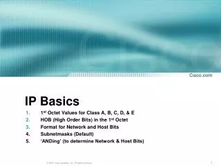
IP address: 32 bits network part (high order bits) host part (low order bits) Defined by class of IP address? Defined by subnet mask? IP Addressing 4: Network Layer
IP address: 32-bit identifier for host, router interface interface: connection between host and physical link router’s must have multiple interfaces host may have multiple interfaces IP addresses (unicast addresses) associated with interface, not host, router 223.1.1.2 223.1.2.2 223.1.2.1 223.1.3.2 223.1.3.1 223.1.3.27 IP Address Per Interface 223.1.1.1 223.1.2.9 223.1.1.4 223.1.1.3 223.1.1.1 = 11011111 00000001 00000001 00000001 223 1 1 1 4: Network Layer
How to find the networks? device interfaces with same network part of IP address? can physically reach each other without intervening router? 223.1.3.27 223.1.3.1 223.1.3.2 IP Addressing 223.1.1.2 223.1.1.1 223.1.1.4 223.1.1.3 223.1.7.0 223.1.9.2 223.1.9.1 223.1.7.1 223.1.8.1 223.1.8.0 Interconnected system consisting of six “networks” or one network (223.1.*.*)? 223.1.2.6 223.1.2.1 223.1.2.2 4: Network Layer
multicast address 1110 network host 110 network 10 host 32 bits IP Addresses (Classes) given notion of “network”, let’s re-examine IP addresses: “class-full” addressing class 1.0.0.0 to 127.255.255.255 A network 0 host 128.0.0.0 to 191.255.255.255 Unicast B 192.0.0.0 to 223.255.255.255 C 224.0.0.0 to 239.255.255.255 D Multicast 240.0.0.0 to 255.255.255.255 reserved E Reserved 1111 4: Network Layer
Hosts per Class • Class A has ~224 hosts (16777216) • Class B has ~216 hosts (65536) • Class C has ~28 hosts (256) • What class do you think everyone wants? • Suppose you are a company/university etc. Do you expect to need 16777216 hosts? Do you expect to need more than 256? 4: Network Layer
IP Address Space Allocation CAIDA 1998 4: Network Layer
Current Allocation • Interesting to examine current IP address space allocation (who has class A’s ? Etc) • Who has A’s? • Computer companies around during initial allocation (IBM, Apple) • Universities (Stanford, MIT) • Have A and still use other IP address blocks? • CAIDA has info on complete allocation 4: Network Layer
host part network part 11001000 0001011100010000 00000000 200.23.16.0/23 IP addressing: CIDR • Class-full addressing: • inefficient use of address space, address space exhaustion • e.g., class B net allocated enough addresses for 65K hosts, even if only 2K hosts in that network • CIDR:Classless InterDomain Routing • network portion of address of arbitrary length • address format: a.b.c.d/x, where x is # bits in network portion of address 4: Network Layer
Recall: How to get an IP Address? • Answer 1: Normally, answer is get an IP address from your upstream provider • This is essential to maintain efficient routing! • Answer 2: If you need lots of IP addresses then you can acquire your own block of them. • IP address space is a scarce resource - must prove you have fully utilized a small block before can ask for a larger one and pay $$ (Jan 2002 - $2250/year for /20 and $18000/year for a /14) 4: Network Layer
How to get lots of IP Addresses? Internet Registries RIPE NCC (Riseaux IP Europiens Network Coordination Centre) for Europe, Middle-East, Africa APNIC (Asia Pacific Network Information Centre ) for Asia and Pacific ARIN(American Registry for Internet Numbers) for the Americas, the Caribbean, sub-saharan Africa LACNIC (Latin America and the Caribbean) Note: Once again regional distribution is important for efficient routing! Can also get Autonomous System Numbers (ASNs) from these registries 4: Network Layer
Classful vs Classless • Class A = /8 • Class B = /16 • Class C = /24 4: Network Layer
How to get a block of IP addresses?From upstream provider Network (network portion): • get allocated portion of ISP’s address space: ISP's block 11001000 00010111 00010000 00000000 200.23.16.0/20 Organization 0 11001000 00010111 00010000 00000000 200.23.16.0/23 Organization 1 11001000 00010111 00010010 00000000 200.23.18.0/23 Organization 2 11001000 00010111 00010100 00000000 200.23.20.0/23 ... ….. …. …. Organization 7 11001000 00010111 00011110 00000000 200.23.30.0/23 4: Network Layer
200.23.16.0/23 200.23.18.0/23 200.23.30.0/23 200.23.20.0/23 . . . . . . Hierarchical addressing: route aggregation Hierarchical addressing allows efficient advertisement of routing information: Organization 0 Organization 1 “Send me anything with addresses beginning 200.23.16.0/20” Organization 2 Fly-By-Night-ISP Internet Organization 7 “Send me anything with addresses beginning 199.31.0.0/16” ISPs-R-Us 4: Network Layer
200.23.16.0/23 200.23.18.0/23 200.23.30.0/23 200.23.20.0/23 . . . . . . Hierarchical addressing: more specific routes ISPs-R-Us has a more specific route to Organization 1 Organization 0 “Send me anything with addresses beginning 200.23.16.0/20” Organization 2 Fly-By-Night-ISP Internet Organization 7 “Send me anything with addresses beginning 199.31.0.0/16 or 200.23.18.0/23” ISPs-R-Us Organization 1 4: Network Layer
IP Address Allocation • CIDR is great but must work around existing allocations of IP address space • Company 1 has a /20 allocation and has given out sub portions of it to other companies • University has a full class B address • Company 2 has a /23 allocation from some other class B • ALL use the same upstream ISP – that ISP must advertise routes to all these blocks that cannot be described with a simple CIDR network ID and mask! • Estimated reduction in routing table size with CIDR • If IP addresses reallocated, CIDR applied to all, IP addresses reallocated based on geographic and service provider divisions that current routing tables with 10000+ entries could be reduced to 200 entries [Ford, Rekhter and Brown 1993] • How stable would that be though? Leases for all? 4: Network Layer
IP addresses: how to get one? One more time • Hard-coded by system admin in a file • Long with subnet mask, default gateway and DNS server • DHCP:Dynamic Host Configuration Protocol: dynamically get network identity and neighborhood info dynamically, “plug-and-play” 4: Network Layer
DHCP • Automated configuration of IP addresses • DHCP server hands out IP addresses to hosts in a administrative domain • Relieves burdens of system administrators - major factor in lifetime cost of computer systems! • Runs over UDP (ports 67 and 68) • RFC 2131 4: Network Layer
Finding the DHCP server? • Wouldn’t be big improvement if had to configure each host with address of DHCP server! • A little better because at least every machine in a local network gets same info • Hosts send special DHCPDISCOVER message to the special IP address 255.255.255.255 • This is a special IP broadcast address and all other nodes on that network will receive • We’ll see more about special addresses like this 4: Network Layer
DHCP Discover/Offer • Host broadcasts “DHCP discover” msg • Sent to 255.255.255.255 from 0.0.0.0 • Contains a client ID to uniquely identify the client in that network • Usually use MAC address • DHCP server can be configured with a “registered list” of MAC addresses to accept • DHCP server responds with “DHCP offer” msg • Sent from IP address of DHCP server to 255.255.255.255 • Includes ip address, subnet mask, DNS servers, default gateway, length of lease 4: Network Layer
DHCP Request/Ack • Host sends “DHCP request” msg directly to server • Sent to DHCP Server’s IP address • Requests the address and other info offered with DHCP offer or could be requesting the address it was offered last time ( ie before it expires) • Still sent from 0.0.0.0 • DHCP server responds with “DHCP ack” msg • Sent from IP address of DHCP server to 255.255.255.255 • Final confirmation of the ip address, subnet mask, DNS servers, default gateway, length of lease 4: Network Layer
DHCP discover src : 0.0.0.0, 68 dest.: 255.255.255.255,67 yiaddr: 0.0.0.0 transaction ID: 654 DHCP client-server scenario arriving client DHCP server: 223.1.2.5 DHCP offer src: 223.1.2.5, 67 dest: 255.255.255.255, 68 yiaddrr: 223.1.2.4 transaction ID: 654 Lifetime: 3600 secs DHCP request src: 0.0.0.0, 68 dest:: 255.255.255.255, 67 yiaddrr: 223.1.2.4 transaction ID: 654 Lifetime: 3600 secs time DHCP ACK src: 223.1.2.5, 67 dest: 255.255.255.255, 68 yiaddrr: 223.1.2.4 transaction ID: 654 Lifetime: 3600 secs Network Layer
DHCP server on every network? • If there is a DHCP server on the local network to receive the broadcast, then it can respond the host with its IP address, its default router, etc. • Alternatively, can have a DHCP relay agent on each network that knows the address of the DHCP server and will forward the DHCPDISCOVER message 4: Network Layer
Leases • DHCP doesn’t *give* each client an IP address, just lease them for a while • IP addresses aren’t reserved by clients not currently connected to the network • Clients can keep their address by renewing their leases • Some DHCP servers will hand out new address each time (especially to prevent customers running servers) • Dynamic DNS? • Clients typically start renewing ½ way through lease period • Internet wide DHCP to enforce efficient CIDR? 4: Network Layer
Renew lease • Host requests IP address: “DHCP request” msg • Once know the IP address of the DHCP server then just send a request message directly to them • DHCP server sends address: “DHCP ack” msg • Contains same info as an offer 4: Network Layer
DHCP other • DHCP servers and DNS • DHCP servers and routers • What if some machine choose their own IP address in the proper range? Doesn’t stop data from flowing to them (see ARP later) • Unless routers or switches keep list of valid MACs • DHCP and BOOTP • Security problem – attach to network and act like DHCP server – give out all duplicate IPs 4: Network Layer
Unicast vs Broadcast vs Multicast • Unicast Addresses • IP Datagram destined for single host • Type of IP address you normally think of • Class A-C + some special IP addresses • Broadcast • IP Datagram sent to all hosts on a given network • Some unicast network id + special host id • Some part of reserved E class • Multicast • IP Datagram sent to a set of hosts belonging to a “multicast” group or group of interested receivers • Class D • We will return to IP multicast later 4: Network Layer
Broadcast • Basic Idea is “all machines like X” • Net-directed Broadcast • netid.* • All bits in host portion 1’s • 128.1.2.255 is a subnet-directed broadcast with subnet mask 255.255.255.0 but not with 255.255.254.0 • Limited Broadcast • 255.255.255.255 • *.*.*.* • Not forwarded! 4: Network Layer
Other special addresses • Loopback • Specify this host 4: Network Layer
Special Address Summary Note: -1 = all 1’s 4: Network Layer
Note • Broadcast and multicast make sense for UDP and not for TCP • telnet 255.255.255.255 doesn’t make sense 4: Network Layer
IP datagram format IP protocol version Number 32 bits total datagram length (bytes) type of service head. len header length ver length for fragmentation/ reassembly fragment offset “type” of data flgs 16-bit identifier max number remaining hops (decremented at each router) upper layer time to live Internet checksum 32 bit source IP address 32 bit destination IP address upper layer protocol to deliver payload to E.g. timestamp, record route taken, specify list of routers to visit. Options (if any) data (variable length, typically a TCP or UDP segment) 4: Network Layer
IP Header: Version and Header Length • Version number (4-bit ) • 4 for IPv4, 6 for IPv6 • Fields that follow can vary based on this number • Header length (4-bit ) • Number of 32 bit words (24-1 32 bits = 60 bytes) • Includes length of options (40 bytes max) 4: Network Layer
IP Header: TOS • Type-of-service (TOS) field ( 8 bits) • 3 Bit precedence field • 4 TOS bits (only one may be turned on) • Minimize delay • Maximize throughput • Maximize reliability • Minimize monetary cost • 1 unused bit • Many implementations ignore; most implementations don’t allow application to set this to indicate preference anyway 4: Network Layer
IP Header • Total length field (16 bits) • Length in bytes • Max Total length 216-1 = 65535 bytes • Max Data = 65535 –Header Length • Can you really send that much? • Link layer might not be enough to handle that much; Various link layer technologies have different limits • As pass over various link layers, IP datagram will be fragmented if necessary • Total length field will change when fragmented 4: Network Layer
Network links have MTU (max.transfer size) - largest possible link-level frame. Different link types, different MTUs Ex. Ethernet maximum is 1500 bytes, FDDI maximum is 4500 bytes Large IP datagram divided (“fragmented”) within net “Reassembled” only at final destination (even if pass over other links that could handle larger datagram) May be fragmented multiple times One fragment dropped => entire datagram dropped IP Fragmentation & Reassembly fragmentation: in: one large datagram out: 3 smaller datagrams reassembly 4: Network Layer
IP Header: Fragmentation • Fields to manage fragmentation • Identification (16 bits) • “Unique ID” for datagram • Original spec said transport layer would set • Usually set to value of variable in IP layer that is incremented by one for each datagram sent from that host (regardless of destination) • Would wrap every 65535 datagrams • Flags ( 3 bits) • 1 bit used to say whether there are more fragments following this one in the original datagram • 1 bit used to say “do not fragment” (drop and send error message back to source if need to fragment) • Fragment Offset (13 bits) • Give offset of data in this fragment into original datagram 4: Network Layer
length =1500 length =1500 length =4000 length =1040 ID =x ID =x ID =x ID =x fragflag =1 fragflag =1 fragflag =0 fragflag =0 offset =0 offset =1480 offset =2960 offset =0 IP Fragmentation and Reassembly One large datagram becomes several smaller datagrams each with their own IP header!! Note: TCP/UDP header with port numbers etc only in 1st fragment 4: Network Layer
Alternatives to Fragmentation? • IP wants to be able to run anywhere: Make packet size as small as the minimum packet size anywhere along a route • Detection? Min Increases after detection? Least common denominator? • Look before you leap? • Path MTU Discovery = To avoid overhead of fragmentation and reassembly in network, hosts often send a series of probe packets to determine the smallest MTU along a route 4: Network Layer
Path MTU Discovery in TCP • If doing Path MTU Discovery, start with minimum of receiver’s specified MSS or local MTU and set the Don’t Fragment Bit • If ICMP message received indicating that fragmentation was required, then segment size will be reduced • Periodically (every 10 min or so), TCP will try a higher segment size up to the receiver’s MSS to see if new route is being used that would allow larger segments • Not all implementations support this 4: Network Layer
Path MTU Discovery in UDP • Not like TCP where sender sends stream in chunks as they see fit and receiver reads in chunks as they see fit • With UDP, the size of the UDP packet is much more visible to the application • May send with DF bit off • May send with DF bit on and if get ICMP messages then IP on host may fragment before sent but not exposed to application layer to encourage smaller amounts of data sent • Again not all implementations support 4: Network Layer
Exercise • Trace a TCP connection and look at the IP headers • Trace a UDP traffic • Hint: DNS or DHCP good sources of UDP traffic • Questions • Is the Do Not Fragment Bit on? • Look at the Identification flag of subsequent IP datagrams 4: Network Layer
Path MTU Discovery • Look in Ethereal at TCP segments, will see Do Not Fragment Bit is set • If on Ethernet, don’t usually see adjustment • Ethernet has one of the smaller MTUs so never get an ICMP error saying needs to be smaller • If sent from local network with larger MTU might see this activity 4: Network Layer
IP Header: TTL • Time-to-live field / TTL (8 bits) • Initialized by sender; decremented at each hop • If reaches zero, datagram dropped • Limits total number of hops from source to destination (28-1 = 255) • Prevents things like infinite routing loops • Usually set to 32 or 64 • Look at TTL field in Ethereal for incoming traffic and for outgoing traffic • Used by traceroute (more later) 4: Network Layer
IP Header: Protocol • Identifies which upper layer protocol to which IP should pass the data • 8 bits: 28-1 = 255 max number protocols • 1= ICMP • 2= IGMP • 6 = TCP • 17 = UDP • 135-254: Unassigned • Who do you think assigns these numbers? • http://www.iana.org/assignments/protocol-numbers 4: Network Layer
IP Header • Header Checksum • Calculated over IP header • 16-bit one’s complement • When change TTL, checksum updated • Source and destination IP addresses • Options: variable length • Security options • Record route/timestamp (alternative to traceroute) • Loose (strict? )source routing - source can say path it would datagram to take; routers need not support • Options must end on 32 bit boundary – pad of 0 if necessary 4: Network Layer
Used by hosts, routers, gateways to communication network-level information like error notification or querying network conditions Network-layer “above” IP: ICMP msgs carried in IP datagrams ICMP message: type, code, checksum plus typically first 8 bytes of IP datagram causing error ICMP: Internet Control Message Protocol ICMP Message Format 8-bit code 8-bit type 16-bit checksum Contents depends on type 4: Network Layer