Download
1 / 22
220 likes | 345 Vues
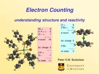
Centre for Advanced Functional Materials and Devices Aberystwyth University & Bangor University, Wales, UK. Progress on the Aberystwyth Electron Counting Array Prof D.A. Evans, Dr. D.P.Langstaff † , Mr. O.R. Roberts, Dr. Xi Zhu. PSD8 Glasgow September 2008. Overview. Technology Overview

E N D
Centre for Advanced Functional Materials and DevicesAberystwyth University & Bangor University, Wales, UK. Progress on the Aberystwyth Electron Counting Array Prof D.A. Evans, Dr. D.P.Langstaff†, Mr. O.R. Roberts, Dr. Xi Zhu PSD8 Glasgow September 2008
Overview Technology Overview Long Array Development Control Electronics Development Application to Diamond Contact Formation
Detector Technology Overview • Readout Device for Microchannel Plate • Custom ASIC • Linear Array of Collection Anodes • Amplifier Discriminators • 16-bit Counters & Readout Circuitry • Ceramic Substrate & MCP Holder • Mounted in Electron Energy Analyser • Floating Control Electronics (ex vacuum)
Long Array Development • Current array • 768 anodes • 19.2mm x 3mm • New Array • New Electron Analyser (SPECS PhoiBOS 100) • 1536 anodes • 38.4mm x 5mm
Long Array Technology Challenges • Yield • Not an issue (Current device yields at 90%) • Reticle Size • Standard 20mm x 20mm reticle • Need ‘stitched’ design (Left + Right) • No active devices across stitch boundaries • Tighter Design Rules over stitch boundary
Long Array Stitching Stitch Boundary
Wafer with 40mm detector chips • 40mm detector • 20mm detector • Test structures
Control Electronics Development • ≈ 2kV across MCP Floating readout system • TCP/IP over fibre optic (10 Base F) • Data Acquisition • Gate Timing • Existing system • Based on ipEngine (Brightstar Engineering) • Programmed in C • 1.5ms/frame (768 pixels @ 2us/pixel) • In development: • Based on National Instruments cRIO • Labview programmable • 0.75 ms/frame (1us/pixel) • Easily re-programmed for special applications
Control Electronics Development New Controller ExistingController
Detector Applications • In-situ study of surface processes: • Contact Formation • Thin Film Growth • In situ XPS/PES • Heated stage (up to 1400 °C) • K-cells + shutter • CLAM4 Analyser (Lab & SRS)
Photoelectron Spectroscopy x-ray electrons • Core level Photoemission • Valence level Photoemission • In-situ and real-time
Contact Formation on Diamond • Important for Diamond based devices • Not predictable • Ohmic Contact • Shottky Diode • Graphitisation • Depends on • Metal • Substrate Doping • Surface Termination • Temperature • Etc, etc
Contact Formation on Diamond • Study by Real Time PES/XPS Lab-based (300W MgKa) • Single crystal, B doped, p-type <100> CVD • Deposit Al with k-cell • Anneal • Monitor peak intensity & position for C1s • D. A. Evans, O. R. Roberts, A. R. Vearey-Roberts, et al., Applied Physics Letters 91, 132114 (2007).
C1s core peak during growth • 3D plot of array data • Pixels calibrated in eV • Shuttered K-cell • Peak Attenuation gives growth mode
C1s core peak during anneal • 3D plot of array data • Pixels calibrated in eV • 1 sec snapshots • Heat Ramp applied • Intensity variation • Peak Shift
C1s core peak during anneal Formation of bulk carbide (Al3C4) Increase in carbon intensity due to Al clustering Abrupt shift in peak position at onset of shottky to ohmic transition
Eliminate Multiple Triggering Charge Cloud Spreading Degrades Spectrum Voting Circuit Post-doc See poster Commercialisation 2 Dimensions Spatial + Energy Angle + Energy Depth + Energy High Flux / Short Pulse Applications Spread electrons over larger area Into the Future
Acknowledgements • Aberystwyth University • Prof. Keith Birkinshaw • Prof. Andy Evans • Adam Bushell, Owain Roberts, Alex Veary-Roberts • SRS Daresbury • Vin Dhanak, Rich Farrow, John Headspith • DTi, EPSRC, KEF, CAFMaD, SRIF