Download
1 / 18
390 likes | 1.09k Vues
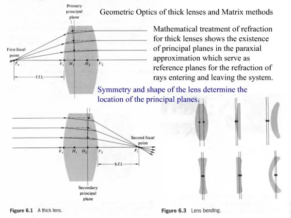
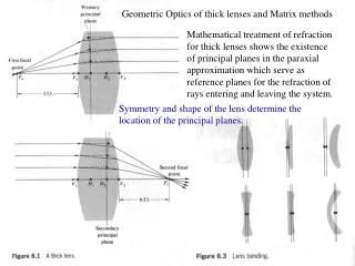
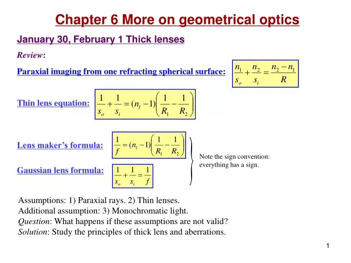
Chapter 6 More on geometrical optics January 30, February 1 Thick lenses Review : Paraxial imaging from one refracting spherical surface: Thin lens equation: Lens maker’s formula: Gaussian lens formula:. Note the sign convention: everything has a sign.

E N D
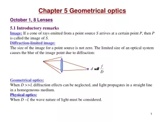
Chapter 6 More on geometrical optics January 30, February 1 Thick lenses Review: Paraxial imaging from one refracting spherical surface: Thin lens equation: Lens maker’s formula: Gaussian lens formula: Note the sign convention: everything has a sign. Assumptions: 1) Paraxial rays. 2) Thin lenses. Additional assumption: 3) Monochromatic light. Question: What happens if these assumptions are not valid? Solution: Study the principles of thick lens and aberrations.
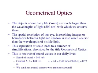
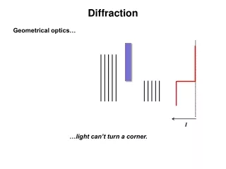
D f Dq Some jargons in photography: Field of view (angle of view): The angle in the object space over which objects are recorded on the sensor of the camera. It depends on the focal length of the lens and the size of the sensor. Depth of field: The region in the object space over which the objects appear sharp on the sensor. f-number(f/#): The ratio of the focal length to the diameter of the entrance pupil: The f/# affects 1) the brightness of the image, 2) the sharpness of the image, and 3) the depth of field. f.o.v. 6.1 Thick lenses and lens systems Thick lenses: When d is not small, the lens maker’s formula and the Gaussian lens formula are not valid. Why thick lens? The image of a distant point source is not a point, but a diffraction pattern because of the limited size of the lenses. Larger D produces clearer images. ~ f D d.o.f. ~ f
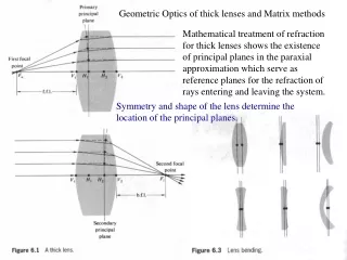
Secondary principle plane Fi V2 V1 H2 H1 b.f.l. Primary principle plane Fo V1 V2 H1 H2 f.f.l. Question: What are the formulas for f and si for a thick lens? Terminology of thick lenses: Principle plane: The plane composed by the crossing points between the incident rays parallel to the optical axis and their emerged rays. Principle points:the intersects between the principle planes and the optical axis. H1 and H2. • Note: • The principle planes are actually curved, while its • paraxial regions forms a plane. • 2) If one surface of the lens is planar, the tangent of • the other surface should be a principle plane. • prove now, and soon again. • 3) Generally • (e.g., plane-convex lenses) to be proved soon.
N1 O A N2 C2 C1 O R1 R2 B Optical center: All rays whose emerging directions are parallel to their incident directions pass through one common point. This point is called the optical center of the lens. proved in chapter 5. Nodal points:The crossing points between the optical axis and the rays passing through the optical center. Coincide with the principle points when both sides of the lens are in the same medium. to be proved soon. Cardinal points of a lens: Two focal points + two principle points + two nodal points. When both sides of the lens are in the same medium: Fi, Fo, H1, H2 are the cardinal points.
yo V1 Fi V2 Fo H2 H1 yi b.f.l. f.f.l. h1 h2 dl xi xo f f si so When Light directed toward the first principle plane will emerge from the second principle plane at the same height. Thick lens equations: When f, so and siare measured from the principle planes, we have Note the new three key rays. The rays inside the lens are virtual. Allare to be proved soon. I hate to believe anything that is not proved by myself. Eqs. 6.1-6.4 h is positive when H is on the right of V. Locating the four cardinal points. Newtonian form: Magnification:
Read: Ch6: 1 Homework: Ch6:4,6,8 Due: February 8
V1 V2 Fi Fo H2 H1 h1 h2 dl f f si so February 4 Combination of thick lenses Thick lens equations: The procedure of locating an image: Everything has a sign. Example (P6.12): R1=4 cm, R2= -15 cm, dl =4 cm, nl =1.5, object =100 cm before lens.
H21 Fi1 Fo2 Fo1 H22 Fi2 Fo H1 H2 H11 Fi H12 f1 f1 f2 f f f2 d Combination of thick lenses: locating the overall cardinal points Note the sign convention for
Read: Ch6: 1 Homework: Ch6:12,13,14 Due: February 15
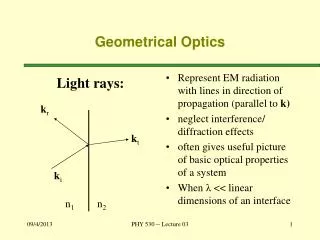
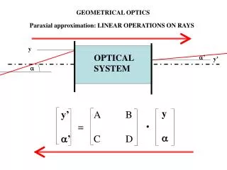
February 6 Ray matrices 6. 2.1 Matrix method Ray tracing:Mathematically following the trace of a ray. Example: Ray tracing of a paraxial, meridional ray traversing a spherical lens. Meridional ray: A ray in a plane that contains the optical axis and the object point. (Opp:skew ray). I. Refraction(at P): Refraction matrix Incident ray vector Refracted ray vector P at a Powerof a refracting surface a ai y R C a nt ni
ar qr yi qi ai V P C R Transfer matrix P2 a2 II. Transfer(from P1 to P2): P1 a1 y2 y1 n d III. Reflection (Mirrors): Mirror matrix
Note: • Variations for the ray vectors and matrixes may exist. • Merit of the current matrices: |R|=|T|=1, and their combinations. • Examples of other definitions of ray vectors and matrices: Another popular form System matrixA of a lens: Transforming an incident ray before the first surface to the emerging ray after the second surface: A→B→C→D D a2 B A C a1 y2 y1 dl nl
Read: Ch6: 2 Homework: Ch6: 16,20,22,23,24 Due: February 15
Eq. 6.2 Eqs. 6.3-4 February 8 Matrix analysis of lenses ApplicationI: Where are the cardinal points (Fi, Fo, H1, H2)? Focusing a parallel beam: P1 P2 a y1 y2 Fi V2 V1 H2 H1 Reversed system matrix
If b =a, then si = so= 0 Nodal points = Principle points Application II: Lens equation P2 P1 a b y2 y1 S P V2 V1 H2 H1 si so Eq. 6.1
Fi1 Fi2 O1 O2 Fo2 Fo1 d f2 f1 ApplicationIII: Thin lens combination: where are the overall cardinal points? Thin lens system matrix
Homework: Starting from Eq. 6.31, please prove Eqs. 6.1-4. Please include detailed drawings showing all the parameters. Due: February 15