Download
1 / 38
400 likes | 724 Vues
GianLuca Israel - gianluca@mporzio.astro.it (INAF – OA Roma) with thanks to Z. Arzoumanian, C. Markwardt, T. Strohmayer (lectures from previous X-ray school editions). The Basics of X-Ray Timing. Why should I be interested? What are the methods and tools? What should I do?. Preface

E N D
GianLuca Israel - gianluca@mporzio.astro.it (INAF – OA Roma) with thanks to Z. Arzoumanian, C. Markwardt, T. Strohmayer (lectures from previous X-ray school editions) The Basics of X-Ray Timing • Why should I be interested? • What are the methods and tools? • What should I do?
Preface • Incipit: time series analysis is a very broad topic, and difficult to cover in one lecture. • Goal: present the most important topics (partially) not discussed in the previous school editions. • Timing analysis may seem a “magic box”, since it can reveal features that are not apparent to the eye in the raw data • Timing “ analysis” is around since a long time: think about day/night, seasons, years, moon phases, etc. Overview • The relevance of timing analysis • Basic light curve analysis (r.m.s.) • Fourier power spectral analysis • Power normalizations and signal searches •Signal detection, signal UL and Asens • Search optimization • A working session example • Cross-Correlation
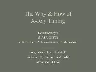
Timing => characteristic timescales = PHYSICS Timing measurements can be extremely precise!! Spin axis Magnetic axis X-rays What can Timing Tell Us? (or, why should I be interested?) • Binary orbits • orbital period • sizes of emission regions and occulting objects • orbital evolution • Rotation of stellar bodies • pulsation periods • stability of rotation • torques acting on system • Accretion phenomena • broadband variability • “quasiperiodic” oscillations (QPOs) • bursts & “superbursts” • Energy dependent delays (phase lags)
- Isolated pulsars (ms–10 s) - X-ray binary systems Accreting pulsars (ms–10000 s) Eclipses (10s min–days) Accretion disks (~ms–years) Transients orbital periods (days-months) - Flaring stars & X-ray bursters - Cataclysmic Variables (s-days) - Magnetars (ms-s) - Pulsating (non-radial) WDs (min-days) There could be variable serendipitous sources in the field, especially in Chandra and XMM observations Typical Sources of X-Ray Variability In short, compact objects (& super-massive black holes?) are, in general, intrinsically variable.
Simplest Measure of Variability • The root-mean-square variability (the same as standard deviation): • Also, it is common to quote the fractional r.m.s., r.m.s./<RATE> Limit: the above def. is bin-size dependent (i.e. You miss any variations smaller than your time bin size) ……. moreover • We must remember that the light curve has Poisson counting noise (i.e. Some randomness), so we EXPECT some variation even if the source has a constant intrinsic intensity.
Chi-Square Test – Hypothesis: the source is intrinsically constant • Can I reject this hypothesis? • Chi-square statistic • If measurements are gaussian (!), the statistic should have a chi-square distribution with (N-1) degrees of freedom. • We can calculate the statistic, compare to tabulated values, and compute confidence in our hypothesis. – An alternative test for variability is the K-S test Limits: • So far, our analysis has focused on the total variability in a light curve. • This method cannot isolate particular timescales of interest. • If we are interested in faster time scales (higher frequencies), we must make a light curve with smaller time bins • The assumption of gaussian statistics eventually fails, when the number of counts per bin is less than ~10, and this method is no longer useful.
Synthetic DATA Light Curves Note that all light curves have 50% fractional r.m.s. variability Implication: TOTAL variability (r.m.s.) does not capture the full information. Its time-scale or (frequency scale) is important as well.
Fourier Analysis • This important technique comes from the theorem that any signal can be written as a sum of complex exponentials: • The ak terms are known as Fourier coefficients (or amplitudes), and can be found by using the Fourier transform (usually a FFT). They are complex-valued, containing an amplitude and phase. • Once we know the Fourier coefficients, we have divided the time series into its different frequency components, and have entered the frequency “domain.” • Parseval proved that: Var[fj] = the left hand side is the total (r.m.s.)2 variance, summed in time; the right hand side is the same total variance, summed over frequencies. The values are known as Fourier powers, and the set of all Fourier powers is a POWER SPECTRUM (PSD). -
Fourier Analysis-2 Light Curves Instrumental noise not included ! When dealing with noise one also need a statistical tool to handle it.
Computing Useful Power Spectra • Power spectra are commonly normalized in two different ways. • The “Leahy” normalization is useful for computing significances (DETECTION). In the following we will refer to it as the default • The “density” normalization is useful for computing fractional r.m.s. Variabilities (PHYSICS) Leahy Normalization • Nph is the total number of photons • With this normalization, the Poisson noise level is distributed like a c2 with n =2NPSD degrees of freedom (in units of counts; NPSD is the number of averaged PSD) – E[c2|n] = n `` 2 for NPSD=1 - s[c2|n] = sqrt(2n) 2 for NPSD=1 noisy
Example: Accreting Pulsar, orbit, tiME delays XTE J1751-305: accreting ms pulsar. Ex:Period drift testifies of an orbit with period of ~40min ~2
Example: QPOs from NS Binaries Sub-ms oscillations seen from > 20 NS binaries Sco X-1 • Frequencies saturate to a maximum. This is likely the signature of the ``innermost stable circular orbit'' around a neutron star, a radius predicted by general relativity inside of which matter must inexorably spiral down to smaller radii
Example: Magnetar sub-ms QPOs The shortest period in (X-ray) astronomy • SGR1806-20 Giant Flare (Dic 2004) • A sequence of QPO frequencies was detected: 18, 29, 92 and 150, 625, and 1840 Hz! • Amplitudes in the 5 – 11% range. • Likely interpretation: A sequence of toroidal modes ~2
Power Spectrum main parameters If your light curve has N bins, with bin size Δt and total duration T, (NOT effective exposure time) then: • The smallest frequency you can sample is nmin = 1/T : this is also the frequency separation between powers or frequency resolution) • The largest frequency you can sample is nmax = 1/(2Δt) (this is the “Nyquist” limiting frequency) • nminand nmax can be changed arbitrarly in order to study the continuum and narrow (QPOs/coherent signal) components of the PSD Example: Δt=72s nmax=1/(2Δt)~7e-3 Hz T=74000s nmin= 1/T ~1.4e-5 Hz T/Δt ~1024 bins
The detection process in a psd • The process of detecting something in a power spectrum against the • background of noise has several steps: • o knowledge of the probability distribution of the noise powers o The detection level: Number of trials (frequencies and/or sample) o knowledge of the interaction between the noise and the signal powers (determination of the signal upper limit) o Specific issues related to the intrinsic source variability (non Poissonian noise) o Specific issues related to a given instrument/satellite (spurious signals – spacecraft orbit, wobble motion, large data gaps, etc.)
Noise probability distribution For a wide range of type of noise (including that of counting photon detectors used in X-ray astronomy), the noise powers Pj,noise follow a c2 distribution with n=2NPSD degrees of freedom. However, for n=2 it reduces to Correspondingly, the signal detection process results in defining a Pthre, such that the probability of having Pj,noise > Pthres is small enough (according to the c2probability distribution) Ex: a power of 44 (in a white noise PSD) has a probability of e-44/2=3x10-10 of being noise. Raw data from a 106 FF of 1 PSD Theoretical c2 dist.
the search threshold and Ntrials - We define a priori a confidence level (1-e) of the search (typically • 3.5s), corresponding to a power P=Pthres which has a small probability • e to be exceeded by a noise power - A crucial consideration, occasionally overlooked, is the number of • trial powers Ntrial over which the search has been carried out o Ntrial = to the powers in the PSD if all the Fourier frequency are considered; o Ntrial < than the powers in the PSD if a smaller range of frequencies has been considered; o Ntrial moltiplied by the number of PSD considered in the project Ex: the previous probability of 3x10⁻¹⁰ has to be multiplied by 1.048.000 trial frequencies and 1 PSD Prob*Ntrial= 3x10-10*1.048.000 =3x10⁻⁴ Still significant!!
ULs and THE sensitivity to the signal If no Pj > Pthres, it is useful to determine an upper limit to any signal power based on the OBSERVED properties. This is given by: PUL=Pmax-Pexceed , where Pmax is the largest actually observed power in the PSD and Pexceed is a power level which has a large probability to be exceeded by any Pj,noise. It is sometimes useful to predict the capabilities of a planned experiment in terms of sensitivity to signal power. This is calculated based on the EXPECTED probability distribution of the noise. Psens=Pthres-Pexceed Note that Psens is in a sense the upper limit to PUL. = Pthres Consideration:Psens has to be used reported in proposal. PUL is used when reporting a non detection in raw data.
Implication: signal detection is not possible for less than ~200 photons ! Estimating Asens for Proposals You need the Intensity (cts/s) of the target and the T (s) of obs. corresponding to net counts Nph. Then, a confidence level has to be set (ns) definesPthres Based on know PSD properties one has : relationship between Asens and the Nph Ex: for a source of Intensity of 5ct/s, an exposure of T=100ks Nph =5e+5cts and Pthres~40 for 3.5s c.l. (256000 Ntrial) Asens= [2.6*40/(0.773*5e+5)]^0.5=1.6%
Intrinsic non-Poissonian noise Many different classes of X—ray sources show aperiodic variability which translates into non-Poissonian noises (red-noise, blue-noise, low frequency noise, shot noise, etc.). Implication: powers are not distributed anymore like a c2 with n d.o.f. no statistical tools to assess the significance of power peaks.
Intrinsic non-Poissonian noise-2 Three different but similar approaches: (1) Rebin of the original PSD, (2) Average of more PSD by dividing the light curve into intervals, (3) Evaluation of the PSD continuum through smoothing. The common idea is to use the information of a sufficiently high number of powers such that it is possible to rely upon a known distribution of the new powers and/or continuum level (c2 or Gaussian or combination). Note that the the processes above modify the PSD Fourier resolution (1/T), but leave unchanged the maximum sampled n (1/2Dt) (1) (2) (3)
Intrinsic non-Poissonian noise-3 If M spectra are considered and/or W contiguous frequencies are averaged, the new variable (in cases 1 and 2) will be distributed like a rescaled c2/MW with 2MW d.o.f. In practice, everything is rescaled in order to have E[c2|2MW]= 2MW/MW=2 . Therefore s[c2|2MW]=sqrt(2MW)/MW less noisy !! Note that for MW>30÷40 the c2 Gaussian Implications: the noise scatter is largely reduced and faint and “extended” signals may be now detected.
signal detection optimization The presence of the x2/sin2x term in the amplitude relationship implies a strong correlation between signal power and its location (in terms of Fourier nj) with respect to nNyq . The power-signal response function Decreases of 60% (from 1 to 0.405) from the 1st and last freq. Implications: When searching for coherent o quasi-coherent signals It is important to use the original (if binned time series) or minimum (if arrival time series) time resolution nNyq = const.
signal detection optimization-2 In the greatest part of the cases the signal freq. nsig is not equal to the Fourier freq. nj. The signal power response as a function of the difference between nsign and the closest nj , is again a x2/sin2x term which varies between 1 and 0.5: for a coherent periodicity 1 means that all the signal power is recovered by the PSD, 0.5 means that the signal power is equally distributed between two adjacent Fourier frequencies nj. Implications:When searching for strictly coherent signals it is important to rely upon the original/maximum Fourier resolution (1/T) do not divide the observation in time sub-intervals.
optimizing for the signal shape Similar reasoning shows that the signal power for a feature with finite width Dn drops proportionally to 1/MW when degrading the Fourier resolution. However, as long as feature width exceeds the frequency resolution, Dn > MW/T , the signal power in each Fourier frequency within the feature remains approx. constant. When Dn < MW/T the signal power begins to drop. Implications:The search for QPOs is a three step interactive process. Firstly, estimate (roughly) the feature width. Secondly, run again a PSD by setting the optimal value of MW equal to ~T Dn. Two or three iterations are likely needed. Finally, use c2hypothesis testing to derive significance of the feature, its centroid and r.m.s. Dn no
What to do Step 1.Barycenter the data: corrects to arrival times at solar system’s center of mass (tools: fxbary/axbary depending on the given mission). Correct for binary orbital param. (if any) Step 2. Create light curves with lcurve for eachsource in your field of view inspect for features,e.g., eclipses, dips, flares, large long-period modulations. lcstatsgive statistical info on the light curve properties (including r.m.s) Step 3. Power spectrum. Run powspec or equivalent and search for peaks. If no signal calculate AUL(or Asens) If a peak is detected infer nsign One peak likely sinusoidal pulse profile More peaks complicated profile Example:nsign = 0.18 Hz Psign = 5.54s T~48ks
What to do-2 Step 4. Use efsearch (P vs c2) to refine the period. Step 1 if you already know the period. Note that efsearch uses the Fourier period resolution (FPR), P2/2T, as input default. It depends from P !!! To infer the best period the FPR has to be overestimated by a factor of several (ex. 20). Fit the resulting peak with a Gaussian and save the central value and ite uncertainty. OK for period, not good for its uncertainty (which is the FPR) Example:for a signal at 5.54s and T=48ks FPR=3.2e-4s FPR input = 3.2e-4/20=1.6e-5s GC= (-1.5±0.1)x10-5s (1s c.l.) P=5.540368-0.000015 = 5.540353 s For the uncertainty is often used the GC error x 20 (the overestimation factor used in input). DP= 0.1x10-5 x 20 s = 2x10⁻⁴ s Final Best Period: 5.5404(2) s (1s c.l.)
What to do-3 • Step 5. Use efold to see the modulation. Fit it • withone or more sinusoids. Infer the pulsed • fraction (several definitions) and/or the • r.m.s. Remove the BG (it works like unpulsed flux). • Step 4b.Apply a phase-fitting technique to your • data (if enough photons). Use efold and save • the sinusoid phase of pulse profiles obtained in • 4 or more time intervals. Plot and fit Time vs • Phase with a linear and quadratic component - If the linear is consistent with 0 the input P • is OK - If a linear component is present the input P is wrong . Correct and apply again the technique. Ex: Example:Best Period: 5.54036(1) s 1s c.l. A factor of ~20 more accurate thanefsearch
MORE on phase-fitting • It provides a phase coherent timing solution which • can be extended in the future and in the past • without loosing the information on the phase, • therefore, providing a tool to study small changes • of signals on long timescales. • - A negative quadratic term in the phase residuals • implies the period is decreasing - A positive term corresponds to an increasing • period • This method is often used in radio pulsar • astronomy. (1) (2) Examples:(1) a shrinking binary – orbital period decreasing at a rate of dP/dt=1ms/yr≈-3x10-11s/s (2) An isolated neutron star spinning down at a rate of dP/dt≈1.4x10-11s/s
Cross-correlations The cross-correlation measures how closely two different observables are related each other at the same or differing times. It also gives information on possible delays or advances of one variables with respect to the other (in practical cases one deals with times or phases). Example:CCF obtained with crosscor. Two simultaneous light curves of a binary system in two different energy intervals (soft and hard). The CCF peaks at positive x and y: the two variables are correlated and the hard variability follows the soft one. Dt=13±2s (1s c.l.). It is often useful to cross check the CCF results with the spectral information or any other useful timing result.
Cross-correlations-2 Example: The folded light curves in the soft (black) and hard (gray) bands confirm the presence of a possible delay S H The study of the energy spectrum clearly reveals the presence of two distinct components (BB+PL) in the soft (S) and hard (H) energy bands considered for in the CCF analysis. The CCF result is reliable/plausible !
Cross-correlations-3 Further considerations:CCF may be also applied to data taken in rather different bands (i.e. optical and X-ray) for a given source. Example:Same source as before, CCF obtained for the optical and X-ray folded light curves (obtained with efold) over a 4-years baseline. Pseudo-simultaneous data: same phase coherent time solution used. The CCF peaks at positive x and negative y: the optical and X-ray data are anti-correlated with the optical one proceeding the X—rays by 0.16 in phase.
Pulsar (coherent pulsation) searches are most sensitive when no rebinning is done (ie., you want the maximum frequency resolution), and when the original sampling time is used (i.e. optimizing the signal power response). Always search in all serendipitous sources (Nph>300) QPO searches need to be done with multiple rebinning scales. In general, you are most sensitive to a signal when your frequency resolution matches (approximately) the frequency width of the signal. CCF: it is worth using it to study the relation among different energies Cross-check with spectral information Beware of signals/effects introduced by - instrument, e.g., CCD read time - Pile-up (wash-out the signal) (check/add keyword TIMEDEL) - Orbital binary motion ( “ ) - Dead time - The use of uncorrect GTIs - Orbit of spacecraft (for single and merged simult. - Telescope motion (wobble,etc.) light curves) - Data gaps Tips
Tips-2 Right GTI table Wrong/no GTI table Right TIMEDEL keyword Wrong/no TIMEDEL keyword
Suggested Reading • - van der Klis, M. 1989, “Fourier Techinques in X-ray Timing”, in Timing • Neutron Stars, NATO ASI 282, eds. Ögelman & van den Heuvel, • Kluwer • Superb overview of spectral techniques! - Press et al., “Numerical Recipes” - Clear, brief discussions of many • numerical topics • - Leahy et al. 1983, ApJ, 266, p. 160 - FFT & PSD Statistics • - Leahy et al. 1983, ApJ, 272, p. 256 - Epoch Folding • - Davies 1990, MNRAS, 244, p. 93 - Epoch Folding Statistics • - Vaughan et al. 1994, ApJ, 435, p. 362 - Noise Statistics • - Israel & Stella 1996, ApJ, 468, 369 – Signal detection in “noisy” PSD - Nowak et al. 1999, ApJ, 510, 874 - Timing tutorial, coherence • techniques For more questions: gianluca@mporzio.astro.it
Estimating Variability for Proposals To estimate amplitude of variations, or exposure time, for a desired significance level… • Broadband noise: • r2 = 2n√ ∆/I√ T • wherer —RMS fractionn—number of “sigma” of statistical significance demanded ∆ —frequency bandwidth (e.g., width of QPO)I —count rateT —exposure time • Coherent pulsations: • fp = 4 n/I T • Example: • X-ray binary, 0–10 Hz, 3 detection, 5 ct/s source, 10 ks exposure 3.8% threshold RMS
Plot PDS Use 2 hypothesis testing to derive significance of features Rebin PDS as necessary to optimize significance If detected with good significance, fit to simple-to-integrate model(s), e.g., gaussian or broken power-law, lorentzians. Compute RMS Is the variability time dependent, energy dependent? Step 3. Broadband feature(s) found? Refined analysis best done interactively (IDL? MatLab?).