Download
1 / 20
210 likes | 510 Vues
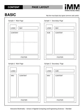
Basic. Controller PLC / PC. Dupline (or other Fieldbus) Installation. Traditional Installation. Field Devices Sensors, Switches, Valves, Contactors, Drives etc. Typical Automation System. General Fieldbus Advantages. Reduced Installation Cost Reduced Cable Cost

E N D
Basic Jens Neigaard
Controller PLC / PC Dupline (or other Fieldbus) Installation Traditional Installation Field Devices Sensors, Switches, Valves, Contactors, Drives etc. Typical Automation System Jens Neigaard
General Fieldbus Advantages • Reduced Installation Cost • Reduced Cable Cost • Reduction in maintenance cost • Increased flexibility • Capacity for more signals Jens Neigaard
Basic components: The twisted pair Signal Common Jens Neigaard
Basic Components: The Channel Generator Jens Neigaard
Basic Components: The Transmitter Jens Neigaard
Basic Components: The Receiver Jens Neigaard
Dupline Addressing Scheme Channels: 1 ... 8 I/OAddresses: A1, A2, A3 .. A8, B1, B2 .. P7, P8 Groups: A ... P Jens Neigaard
Dupline Address Coding Device: GAP1605 Jens Neigaard
Dupline used for wire replacement A1 A2 A4 A3 A2 A4 A1 A3 A1 A4 A3 A3 A2 FMK 8 Channel Generator A1 A2 A4 Jens Neigaard
Receiver Transmitter A1 A5 A1 A5 A1 A5 A1 A5 Transmitter Transmitter n-Remote Transmitters have Effect on One Central Receiver Channel Generator 64 Jens Neigaard
Transmitter Receiver A1 A5 A1 A5 A1 A5 A1 A5 Receiver Receiver A Central Transmitter has Effect on n-Remote Receivers Channel Generator 64 Jens Neigaard
Carlo Gavazzi Dupline Carlo Gavazzi Dupline Dupline Standard Housings Jens Neigaard
Dupline Digital I/O-modules • Different input Types • Contact /NPN Transistor • Voltage • Different output Types • Relay • NPN Transistor • PNP Transistor • Different number of I/O’s • H-Housings, D-Housings and Open PCB • Different supply voltages Jens Neigaard
MODE: DIGITAL 1 GROUP 1 3 7 8 7 Dupline Test Unit: GTU8 Monitoring of Channel Status’ in a Selected Channel Group Dupline Test Unit GTU 8 Display of Channel- Status’ A 1 - 3 - - - - 8 Mode Enter Select Channel- Group 8 Force Channels to ON (monostable) 4 5 6 1 2 3 Jens Neigaard
Dupline has free Topology Jens Neigaard
Dupline Cables • Single (twisted)pair of wires • Shield not required • Recommended min. cross sections • Long distance: 1.5mm2 • Medium distance:0.8 - 1.0 mm2 • Short distance:0.35 mm2 • Low capacitance for longdistances • (preferably < 80 nF/km) Jens Neigaard
Dupline Installation • Never connect DuplineCommon • to Ground • Treat the Dupline cable as a signal wire • Use DT01 termination unit for • distances > 1.5 km • Check correct wiring during • installation Jens Neigaard
Cable Splicing / Isolation • Use soldering splices • Splices must be water tight • No leakage or connection between wires or • fromwires to ground Jens Neigaard
Rules for Dupline-powered Devices • The total current consumption must not exceed max current output of the channel-generator: • G34900000:Max. 70 mA • G38000015: Max. 130 mA • b) The total current consumption in the network multiplied bythe cable loop resistance must not exceed 2 V • An example: 2 km 1.0 sq.mm twisted pair is used. G50101106 is used both with input and LED • The resistance of a 1.0 sq.mm.core is app. 20 Ohms/km. • With a wire length of 2 km the resistance per wire is 40 Ohms • With the 2 Dupline wires the total resistance is 2 x 40 ohms = 80 Ohms. • This means that the max total current is 2 V / 80 Ohms = 25 mA. • One G50101106 with LED function uses 1.2 mA • Max Number of G50101106 = 25 mA / 1.2 mA = 20 units • If the LED is not used the current per G50101106 is only 0.15 mA so in this case the result is: • Max number of G50101106's = 25 mA / 0.15 mA = 166 units. Jens Neigaard