Download
1 / 80
820 likes | 1.04k Vues
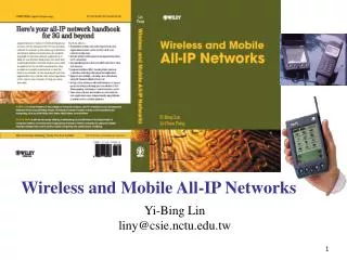
Wireless and Mobile All-IP Networks. Yi-Bing Lin liny@csie.nctu.edu.tw. Contents [1/3]. Chapter 1: Short Message Service and IP Network Integration Chapter 2: Mobility Management for GPRS and UMTS Chapter 3: Session Management for Serving GPRS Support Node

E N D
Wireless and Mobile All-IP Networks Yi-Bing Lin liny@csie.nctu.edu.tw
Contents [1/3] • Chapter 1: Short Message Service and IP Network Integration • Chapter 2: Mobility Management for GPRS and UMTS • Chapter 3: Session Management for Serving GPRS Support Node • Chapter 4: Session Management for Gateway GPRS Support Node • Chapter 5: Serving Radio Network Controller Relocation for UMTS
Contents [2/3] • Chapter 6: UMTS and cdma2000 Mobile Core Networks • Chapter 7: UMTS Charging Protocol • Chapter 8: Mobile All-IP Network Signaling • Chapter 9: UMTS Security and Availability Issues • Chapter 10: VoIP for the Non-All-IP Mobile Networks • Chapter 11: Multicast for Mobile Multimedia Messaging Service • Chapter 12: Session Initiation Protocol
Contents [3/3] • Chapter 13: Mobile Number Portability • Chapter 14: Integration and WLAN and Cellular Networks • Chapter 15: UMTS All-IP Network • Chapter 16: Issues on IP Multimedia Core Network Subsystem • Chapter 17: A Proxy-based Mobile Service Platform
Chapter 1:Short Message Service and IP Network Integration GSM SMS Network Architecture
SMS-IP Integration: SM-SC-based In most commercial implementations, SMS and IP networks are integrated through SM-SC. Mobile Network IP Network SM-SC Gateway
Mobility and Session Management • Three types of mobility: radio mobility, core network mobility and IP mobility • Radio mobility supports handoff of a mobile user during conversation • Core network mobility provides tunnel-related management for packet re-routing in the core network due to user movement • IP mobility allows the mobile user to change the access point of IP connectivity without losing ongoing sessions. • Session management maintains the routing path for a communication session, and provides packet routing functions including IP address assignment and QoS setting.
Chapter 4:Session Management for Gateway GPRS Support Node • The GGSN plays the role as a gateway, which controls user data sessions and transfers the data packets between the UMTS network and the external PDN. • Themeta functions implemented in the GGSN are described as follows: network access control, packet routing and transfer, and mobility management.
Chapter 5:Serving Radio Network Controller Relocation for UMTS DriftRNC Serving RNC Serving RNC
Lossless SRNC Relocation • In 3GPP TS 23.060, a lossless SRNC relocation procedure was proposed for non-real-time data services. 1. The source RNC first stops transmitting downlink packets to the UE, and then forwards the next packets to the target RNC via a GTP tunnel between the two RNCs. 2. The target RNC stores all IP packets forwarded from the source RNC. 3. After taking over the SRNC role, the target RNC restarts the downlink data transmission to the UE. • No packet is lost during the SRNC switching period. • Real-time data transmission is not supported because the IP data traffic will be suspended for a long time during SRNC switching.
Fast SRNC Relocation – Stage I • Stage I (the same as Stage I in SD) initiates SRNC relocation. • The IP packets are delivered through the old path: UENode B2target RNC source RNCSGSN1GGSN • Steps 1 and 2: Source RNC initiates SRNC relocation by sending Relocation_ Required to SGSN1. • Step 3: SGSN1 sends Forward_Relocation_ Request to request SGSN2 to allocate the resources for the UE. • Step 4: SGSN2 send Relocation_Request with RAB parameters to the target RNC. After all necessary resources are allocated, the target RNC send Relocation_Request_ Acknowledge to SGSN2.
Fast SRNC Relocation – Stage II • GGSN routes the downlink packets to the old path receiving Update_PDP_Context_ Request. • After GGSN has received the message, the downlink packets are routed to the new path GGSNSGSN2target RNC. • The “new” packets arriving at the target RNC are buffered until the target RNC takes over the SRNC role. • Step 5: SGSN2 sends Update_PDP_Context_ Request to GGSN. GGSN updates the corresponding PDP context, and the downlink packet routing path is switched from the old path to the new path. • Steps 6-7: SGSN2 informs SGSN1 that all resources for the UE are allocated. SGSN1 forwards this information to the source RNC.
Fast SRNC Relocation – Stage III • The Iur link (i.e., the old path) disconnected. The “old” downlink packets arriving at the source RNC later than Step 7 (Relocation_Command) are dropped. • The SRNC role is switched from the source RNC to the target RNC. • Step 8: The source RNC transfers SRNS context (e.g., QoS profile) to the target RNC. • Steps 9 and 10: The target RNC informs SGSN2 that the target RNC will become the SRNC. At the same time, the target RNC triggers the UE to send the uplink IP packets to the target RNC.
Fast SRNC Relocation – Stage IV • The target RNC informs the source RNC that SRNC relocation is successfully performed. Then the source RNC releases the resources for the UE. • Step 11: The target RNC indicates the completion of the relocation procedure to SGSN2, and SGSN2 forwards this information to SGSN1. • Step 12: SGSN1 requests the source RNC to release the resources allocated for the old path.
Chapter 6:UMTS and cdma2000 Mobile Core Networks • UMTS and cdma2000 are two major standards for 3G mobile telecommunication. • Two important functionalities of mobile core network are mobility management and session management. • This chapter describes these two functionalities for UMTS and cdma2000, and compare the design guidelines for these two 3G technologies.
cdma2000 CS Domain • BSC connects to the core network through the SDU. • The SDU distributes the circuit switched traffic (e.g., voice) to the MSC. • A1 interface supports call control and mobility management between MSC and BSC. • A2 and A5 interfaces support user traffic and circuit switched data traffic between MSC and BSC.
cdma2000 PS Domain • The SDU distributes the packet switched traffic to PCF and then to the PDSN. • Interfaces A8 and A9 support packet switched data and signaling between PCF and SDU, respectively. • Interfaces A10 and A11 (R-P interface) support packet switched data and signaling between PCF and PDSN. • GRE tunnel is used for data routing in A10 with standard IP QoS. • MIP is used for signaling routing in A11. • The R-P interface also supports PCF handoff (inter or intra PDSN).
PDSN • Maintaining link-layer sessions to the MSs • Supporting packet compression and packet filtering before the packets are delivered through the air interface • Providing IP functionality to the mobile network, which routes IP datagrams to the PDN with differentiated service support • Interacting with AAA to provide IP authentication, authorization and accounting support • Acting a MIP FA in the mobile network • The interfaces among the PDN nodes (i.e., PDSN, HA, AAA) follow the IETF standards.
Protocol Stacks [1/2] • The control plane carries out tasks for MM/SM/SMS. • In cdma2000, the mobility and session tasks are based on the same lower layer protocol (IP based protocols) for user data transportation. • In UMTS, the lower layer protocols supporting MM/SM tasks in the control plane are different from the lower layer protocols in the user plane. • The signaling path between MS and SGSN consists of an RRC connection between MS and UTRAN, and an Iu connection between UTRAN and SGSN.
Protocol Stacks [2/2] • In UMTS, the PS domain services are supported by PDCP in the user plane. • PDCP contains compression methods, which provide better spectral efficiency for IP packets transmission over the radio. • In cdma2000, the header and payload compression mechanism is provided by PPP between MS and PDSN. • Both UMTS RLC and cdma2000 LAC provide segmentation and retransmission services for user and control data. • cdma2000 LAC supports authentication functionality for wireless access, which is equivalent to GPRS transport layer authentication in UMTS.
PPP • In both control and user planes for cdma2000, PPP is carried over the LAC/MAC, and R-P tunnels are utilized to establish the connection between an MS and the PDSN. • In cdma2000, a PPP connection is equivalent to a packet data session, which is comparable to the UMTS PDP context. • In the UMTS control plane, no PPP/IP connection is established between MS and SGSN. Signaling is carried over the RRC and Iu connections. • UMTS user plane provides two alternatives for IP services. • IP is supported by non-PPP lower layer protocols. • IP is supported by PPP. • Dial-up application • Mobile IP is introduced to UMTS
signaling signaling and data a c b f RNC HLR Ga CG MS Node B d g PDN SGSN RNC GGSN Gi Gn e Node B MS UTRAN Core Network CG : Charging Gateway UTRAN : UMTS Terrestrial Radio Access Network GGSN : Gateway GPRS Support Node RNC : Radio Network Controller HLR : Home Location Register SGSN : Serving GPRS Support Node MS : Mobile Station Node B : Base Station PDN : Packet Data Network signaling signaling and data Chapter 7:UMTS Charging Protocol • The GTP’ protocol is used for communications between a GSN and a CG, which can be implemented over UDP/IP or TCP/IP. • Above the GTP’ protocol, a Charging Agent (or CDR sender) is implemented in the GSN and a Charging Server is implemented in the CG.
The GTP’ Service Model • Our GTP’ service model follows the GSM Mobile Application Part (MAP) service model. • A GSN communicates with a CG through a dialog by invoking GTP’ service primitives. • A service primitive can be one of four types: • Request (REQ) • Indication (IND) • Response (RSP) • Confirm (CNF)
GTP’ Connection Setup Before a GSN can send CDRs to a CG, a GTP’ connection must be established between the charging agent in the GSN and the charging server in the CG.
GTP’ CDR Transfer The charging agent is responsible for CDR generation in a GSN. The CDRs are encoded using, for example, the ASN.1 format defined in 3GPP 32.215. The charging server is responsible for decoding the CDRs and returns the processing results to the GSN.
GTP’ Failure Detection In a GSN, an entry in the CG list represents a GTP' connection to a CG. • The CG Address attribute identifies the CG connected to the GSN. • The Status attribute indicates if the connection is “active” or “inactive”. • The Charging Packet Ack Wait TimeTr is the maximum elapsed time the GSN is allowed to wait for the acknowledgement of a charging packet. • The Maximum Number of Charging Packet TriesL is the number of attempts (including the first attempt and the retries) the GSN is allowed to send a charging packet. • The Maximum Number of Unsuccessful DeliveriesK is the maximum number of consecutive failed deliveries that are attempted before the GSN considers a connection failure occurs. • The Unsuccessful Delivery CounterNK attribute records the number of the consecutive failed delivery attempts. • The Unacknowledged Buffer stores a copy of each GTP' message that has been sent to the CG but has not been acknowledged. • A record in the unacknowledged buffer consists of an Expiry Timestampte , the Charging Packet Try CounterNL and an unacknowledged GTP' message.
Path Failure Detection Algorithm The Path Failure Detection Algorithm (PFDA) detects path failure between the GSN and the CG. PFDA worksas follows: Step 1. After the connection setup procedure is complete, both NL and NK are set to 0, and the Status is set to “active”. At this point, the GSN can send GTP’ messages to the CG. Step 2. When a GTP’ message is sent from the GSN to the CG at time t , a copy of the message is stored in the unacknowledged buffer, where the expiry timestamp is set to te=t + Tr. Step 3. If the GSN has received the acknowledgement from the CG before te, both NL and NK are set to 0. Step 4. If the GSN has not received the acknowledgement from the CG before te , NL is incremented by 1. If NL=L, then the charging packet delivery is considered failed. NK is incremented by 1. Step 5. If NK=K, then the GTP’ connection is considered failed. The Status is set to “inactive”.
Chapter 8:Mobile All-IP Network Signaling • Traditional SS7 signaling is implemented in MTP-based network, which is utilized in the existing mobile networks including GSM and GPRS. • In UMTS all-IP architecture, the SS7 signaling will be carried by IP-based network. • The low costs and the efficiencies for carriers to maintain a single, unified telecommunications network, guarantee that all telephony services will eventually be delivered over IP. • This chapter describes design and implementation of the IP-based network signaling for mobile all-IP network.
NETWORK 2 NETWORK 1 STP pair STP pair STP pair A-link C-link D-link B-link E-link Voice/Data Trunk A-link A-link F-link SS7 Signaling Link Trunk SCP SSP SSP SS7 Architecture • Service Switching Point (SSP) is a telephony switch that performs call processing. • Service Control Point (SCP) contains databases for providing enhanced services. • Signal Transfer Point (STP) is a switch that relays SS7 messages between SSPs and SCPs.
SS7 Link Types • Access Links (A-links) connect the SSP/STP or the SCP/STP pairs. • Bridge Links (B-links) connect STPs in different pairs. • Cross Links (C-links) connect mated STPs in a pair. • Diagonal Links (D-links) are the same as the B-links except that the connected STPs belong to different SS7 networks. • Extended Links (E-links) provide extra connectivity between an SSP and the STPs other than its home STP. • Fully-Associated Links (F-links) connect SSPs directly.
OSI Model The SS7 Layers OMAP MAP Application ISUP TCAP Presentation Session Transport SCCP Network MTP3 Data Link MTP2 Physical MTP1 SS7 Protocol Stack
SS7 Protocol Stack: MTP & SCCP • Message Transfer Part (MTP) consists of three levels corresponding to the OSI physical layer, data link layer, and network layer, respectively. • The MTP level 1 (MTP1) defines the physical, electrical, and functional characteristics of the signaling links connecting SS7 components. • The MTP level 2 (MTP2) provides reliable transfer of signaling messages between two directly connected signaling points. • The MTP level 3 (MTP3) provides the functions and procedures related to message routing and network management. • Signaling Connection Control Part (SCCP) provides additional functions such as Global Title Translation (GTT) to the MTP.
SS7 Protocol: ISUP, TCAP, MAP • Integrated Services Digital Network User Part (ISUP) establishes circuit-switched network connections (e.g., for call setup). • Transaction Capabilities Application Part (TCAP) provides the capability to exchange information between applications using non-circuit-related signaling. • Operations, Maintenance, and Administration Part (OMAP) is a TCAP application for network management. • Mobile Application Part is a TCAP application that supports mobile roaming management.
Stream Control Transmission Protocol (SCTP) • IETF Signaling Transport (SIGTRAN) working group addresses the issues regarding the transport of packet-based SS7 signaling over IP networks. • SIGTRAN defines not only the architecture but also a suite of protocols, including the SCTP and a set of user adaptation layers (e.g. M3UA), which provides the same services of the lower layers of the traditional SS7. • Why not TCP ? • TCP provides strict order-of-transmission which causes head-of-line blocking problem. • The TCP socket does not support multi-homing. • TCP is vulnerable to blind Denial-of-Service (DoS) attacks such as flooding SYN attacks.
SCTP Features • Like TCP • To provide reliable IP connection. • To employ TCP-friendly congestion control (including slow-start, congestion avoidance, and fast retransmit) • Unlike TCP • To provide message-oriented data delivery service and new delivery options (ordered or unordered) • To provide selective acknowledgments for packet loss recovery • To use a four-way handshake procedure to establish an association (i.e., a connection). • To offer new features that are particularly for SS7 signaling • Multi-homing • Multi-streaming
Chapter 11:Multicast for Mobile Multimedia Messaging Service • Short Message Service (SMS) allows mobile subscribers to send and receive simple text message in 2G systems (e.g. GSM). • Multimedia Message Service (MMS) is introduced to deliver messages of sizes ranging from 30K bytes to 100K bytes in 2.5G systems (e.g. GPRS) and 3G systems (e.g. UMTS) • The content of an MMS can be text (just like SMS), graphics (e.g., graphs, tables, charts, diagrams, maps, sketches, plans and layouts), audio samples (e.g., MP3 files), images (e.g., photos), video (e.g., 30-second video clips), and so on.
MMS Architecture [2/2] • TheMMS user agent (a) resides in a Mobile Station (MS) or an external device connected to the MS, which has an application layer function to receive the MMS. • The MMS can be provided by the MMS value added service applications (b) connected to the mobile networks or by the external servers (d)(e.g., email server, fax server) in the IP network. • The MMS server (c) stores and processes incoming and outgoing multimedia messages. • The MMS relay (e) transfers messages between different messaging systems, and adapts messages to the capabilities of the receiving devices. It also generates charging data for the billing purpose. The MMS server and the relay can be separated or combined. • The MMS user database (f) contains user subscriber data and configuration information. • The mobile network (g) can be a WAP (Wireless Application Protocol) based 2G, 2.5G or 3G system. Connectivity between different mobile networks is provided by the Internet protocol.