Download
1 / 23
230 likes | 470 Vues
S A D A R S Stevenage And District Amateur Radio Society. The Wheatstone Bridge. S A D A R S Stevenage And District Amateur Radio Society. We are all familiar with modern electrical measuring instruments.

E N D
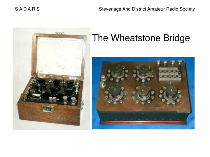
S A D A R S Stevenage And District Amateur Radio Society The Wheatstone Bridge
S A D A R S Stevenage And District Amateur Radio Society We are all familiar with modern electrical measuring instruments. These instruments accurately measure ac and dc volts, ac and dc currents, resistance and other electrical quantities to a high accuracy. But, have you ever thought about how these instruments are calibrated? How do we know, for example, that when the instrument indicates 1.00V, there is actually 1.00V present?
S A D A R S Stevenage And District Amateur Radio Society Before the arrival of the Digital Multimeter (DMM), galvanometers such as the moving coil meter, were the main way of measuring electrical quantities. Here, a coil is suspended in a permanent magnet field and when a current is passed through that coil it generates its own magnetic field. These fields then react with each other so causing a mechanical force to exist between them. With the aid of a spring and pivots, the coil rotates with respect to the permanent magnet and a pointer attached to the coil also moves. Galvanometer – a device that responds to the application of an electrical current
S A D A R S Stevenage And District Amateur Radio Society Early galvanometers often included lens and mirror assemblies to shine a spot or vertical beam of light onto a scale, to magnify the mirror movement.
S A D A R S Stevenage And District Amateur Radio Society The galvanometer by itself is only a device that provides a response to a small applied current. How do we change its sensitivity so that it can respond to a larger current? How can we change its arrangement so that it can indicate a voltage level, rather than a current level? How can we change its arrangement such that it can be used to measure other electrical quantities such as resistance? The fundamental method of adapting the galvanometer to do these jobs is to use resistors as either shunts or multipliers (or a combination of both).
S A D A R S Stevenage And District Amateur Radio Society Resistors – the main devices used to modify the galavanometer’s fundamental function into a more usable format. But then, how to know what resistance your resistor presents? Remember, in the early days of electrical engineering people did not have accurate instruments to check the accuracy of other instruments – accurate measurements had to ‘start somewhere’. What was needed was a method to measure (or compare) resistor values without the need for a calibrated indicator such as a galvanometer. A galvanometer responds to the application of an electrical current, so if the galvanometer indicates no response, there must be no electrical current applied to it (assuming no losses within the ‘mechanics’ of the galvanometer). This is where the Wheatstone Bridge comes into play because it relies on measuring resistance under the condition of zero current through the galvanometer – so the galvanometer does not have to be calibrated, it just needs to be an indicator.
S A D A R S Stevenage And District Amateur Radio Society The potential divider R1 & R2 The voltage Vx with respect to 0V common depends upon the battery voltage and the relative resistance values of R1 and R2. Vx = V+ x R2 (R1 + R2) Notice that it is the ratio of the resistances R1 to R2 that provides the result, not their absolute values.
S A D A R S Stevenage And District Amateur Radio Society The potential divider, calculation and demonstration Each resistor R1 to R10 is 1kW Take the 7V output tap, for example; Vx = V+ x R2 from previous slide (R1 + R2) V+ = 10V `R1` = R1 + R2 + R3 = 3kW `R2` = R4 + R5 + R6 + R7 + R8 + R9 + R10 = 7kW So Vx = 10V x 7kW = 70VkW = 7V 3kW + 7kW 10kW Try the calculations yourself at different tappings.
S A D A R S Stevenage And District Amateur Radio Society If we now add a second potential divider, R3 & R4 and make the ratio of R3 to R4 the same as R1 to R2, then Vx = V+ x R2 (R1 + R2) Vy = V+ x R4 (R3 + R4)
S A D A R S Stevenage And District Amateur Radio Society But Vx must be the same as Vy because the resistor ratios are the same, thus V+ x R2 = V+ x R4 (R1 + R2) (R3 + R4) The same battery supply is being used, so the V+ term cancels out leaving us with R2 = R4 _ (R1 + R2) (R3 + R4) So, if we know the resistance values of R1, R2 and R3, we can calculate the resistance of R4
S A D A R S Stevenage And District Amateur Radio Society Now the mathematics bit, from the previous slide , R2 = R4 . (R1 + R2) (R3 + R4) and remembering that whatever is done to one side of the equation has to be done to the other side of that equation So, R2 x (R3 + R4) = R4 x (R1 + R2) (above equation cross multiplied) R2 x R3 + R2 x R4 = R4 x R1 + R4 x R2 (bracket terms expanded) But R2 x R4 appears on both sides of the equation and so cancels out Thus, R2 x R3 = R4 x R1 Or R4 = R2/R1 x R3 and R2/R1 is the ratio between these 2 resistors But if R1 = R2, then R4 = R3 (which is a special case)
S A D A R S Stevenage And District Amateur Radio Society Demonstration – equal taps on the chain If we now add a second potential divider to the one shown earlier, connected to the same power supply; we can firstly show that each tapping on the second chain again provides 1V steps and secondly show that if we connect a meter across the same tap point on each chain (for example the 6V tap on the left hand chain to the 6V tap on the right hand chain), the meter indicates zero (any small errors are due to the tolerances of the components used in this demonstration)
S A D A R S Stevenage And District Amateur Radio Society We now have the familiar Wheatstone Bridge circuit, which is exactly the same circuit as the one shown by the previous slide. The unknown resistance is connected in one arm and the variable resistance changed until the galvanometer indicates zero.
S A D A R S Stevenage And District Amateur Radio Society Early Wheatstone bridge designs had slider contacts on resistive conductors so the ratio (of R1 and R2) could be determined by using a ruler.
S A D A R S Stevenage And District Amateur Radio Society Another arrangement to sliders on a bar was to calibrate the resistive wire along its length
S A D A R S Stevenage And District Amateur Radio Society Later Wheatstone bridge designs used the earlier models to calibrate individual resistors, which could then be connected into the bridge circuit to suit the measurements and ratios as desired, expanding the available ranges. Here, you can now begin to see the process of measuring and calibrating newer designs by using previous models – which eventually leads us to the measuring devices that we use today.
S A D A R S Stevenage And District Amateur Radio Society Demonstration – the Wheatstone Bridge From the earlier slides R4 = R2/R1 x R3 If R1 = R2, then R4 = R3 For R1 and R2 we use the 10 resistor chain For R3 we use a 10 turn 10kW potentiometer where the 10 turn dial indicates its resistance setting. We connect an unknown resistor into the R4 position, switch on the power supply and then adjust the potentiometer until the meter indicates zero. The potentiometer setting lets us work out R4
S A D A R S Stevenage And District Amateur Radio Society So far, we have been energising the bridge from dc supply, which is how the early engineers used this instrument, but will it work with an ac supply? Why should we consider an ac supply anyway? The answer to this question relates to the other passive components that we use, capacitors and inductors, since these components respond to ac, rather than dc, signals. The most significant problem associated with a Wheatstone Bridge and ac supplies is the detecting device, where a dc galvanometer will not respond to ac signals. There were meter movements available like the moving iron type which do respond to ac, but these tend to be insensitive devices. These days it is quite easy to rectify an ac signal, so as to produce a dc signal that will activate a galvanometer, but remember that in the early days, before thermionic diodes and valves were invented, such rectification was not an easy task.
S A D A R S Stevenage And District Amateur Radio Society This is the galvanometer circuit that is used in the demonstration unit for dc indications. The added resistor and diodes are present to prevent damage to the meter when the bridge is ‘way off’ balance. The resistor limits the meter current and the silicon diodes conduct when the voltage applied to the inputs exceeds about 0.7V in either polarity. When the bridge is in balance the voltage across the inputs is zero, so the diodes have no effect. The resistor reduces the meter’s sensitivity and so could be shorted out near balance to improve circuit sensitivity. Commercial Wheatstone bridges sometimes included such a switch.
S A D A R S Stevenage And District Amateur Radio Society This is the entire meter circuit of the demonstration unit. The 4 added germanium diodes are switched into circuit when ‘ac’ is selected and convert the ac input signal to dc. The forward voltage drop of these germanium diodes reduces the sensitivity of the meter, especially near zero input. Bridge sensitivity, and thus the accuracy of the balance obtained, would be improved by either increasing the input signal to the bridge (which has the adverse effect of increasing dissipation in the bridge components) or by adding an ac amplifier between the bridge output and the meter circuit.
S A D A R S Stevenage And District Amateur Radio Society This is a schematic of a practical capacitor measuring bridge. The ac signal source frequency is adjusted to suit the capacitor being measured (higher frequency for lower value capacitors). The potentiometer is used for one complete arm of the bridge (rather than just one element of the bridge) and is calibrated accordingly. See the capacitor measurement box being passed around.
S A D A R S Stevenage And District Amateur Radio Society This talk has shown us some of the history of the Wheatstone Bridge and how its use has led up to the measuring devices that we use today. Are there any questions or further explanations needed by anyone? Now is the time for you to come up to the demonstration unit and to make some measurements yourselves.