Download
1 / 51
520 likes | 810 Vues
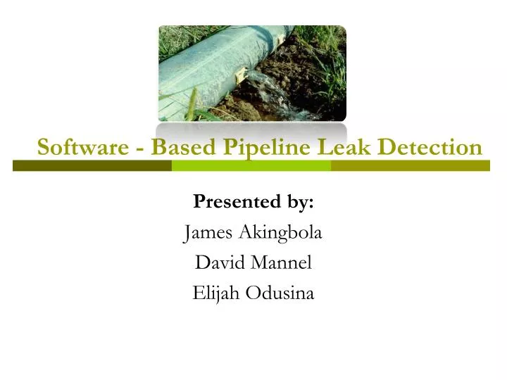
Software - Based Pipeline Leak Detection. Presented by: James Akingbola David Mannel Elijah Odusina. Overview. Introduction. Pipelines used as bulk carriers of crude oil and natural gas Used in water distribution systems Results of Leakages include: Loss of product

E N D
Software - Based Pipeline Leak Detection Presented by: James Akingbola David Mannel Elijah Odusina
Introduction • Pipelines used as bulk carriers of crude oil and natural gas • Used in water distribution systems • Results of Leakages include: • Loss of product • Environmental hazards • Loss of life
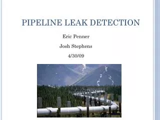
Introduction Gas pipeline explosion in the Ukrainian village of Luka south of the capital Kiev May 7, 2007
Methods of leak detection • Hardware Method: This method is used to detect leaks with instrumentation outside the pipeline. • Software Method: This method uses different instruments to monitor internal parameters (such as pressure, flow, temperature) that infer product release. It is also known as computational pipeline monitoring (CPM).
Hardware Method • Acoustic Emissions • Fiber Optic Sensing • Vapor Monitoring • Multi-hop Sensor Wireless Network* * Method developed by OU faculty: Professor Sridhar Radhakrishnan
Hardware Method - Acoustic Emissions * http://www.wavealert.com/Pages/sys1.html
Pipeline Monitoring: Multi-hop Sensor Wireless Network Professor Sridhar Radhakrishnan Solution Multi-hop wireless sensor network with appropriate sensor fusion technologies. Problem: Develop continuous real-time monitoring of pipelines to determine leak and other structural damages. Importance: Failure of gas pipelines will result in both human, property, and environmental damage. Current Solution: Low flying aircraft, visual inspection, and use of pigs for internal monitoring. Weaknesses: Expensive, non-continuous monitoring, fail-first, fix-later solutions. • Research Issues • Communication in the presence of unreliable sensors • Power aware strategies • Optimal sensor configuration and data fusion School of Computer Science
Hardware Methods • Advantages • Good sensitivity to leak • Very accurate in leak locating • Disadvantages • System costs are usually high • High complexity of installation
Software Methods • Balancing Systems • Uses the principle of mass conservation • Types of Balancing systems • Volume Balance • Compensated Mass Balance • Model Compensated Mass Balance
Software Methods- Balancing Systems • Advantage • It is simple to implement • Cost effective • Disadvantage • Can be affected by instrument error • High rate of false alarms
Software Method - Pressure Analysis • Gradient Intersection method • This method uses SCADA* values to calculate the theoretical hydraulic profile or baseline of the pipe • The presence of a leak can be determined from a specific deviation or combinations of several deviations from the baseline *Supervisory Control and Data Acquisition (SCADA)
Software Method – Gradient Intersection • Advantages • Estimation of leak location can be determined • Disadvantages • Dependent on instrument sensitivity. • Smaller leaks typically take longer time to detect. • Does not give magnitude of leak
Software Method - RTTM • Real Time Transient Modeling (RTTM) • Involves computer simulation of pipeline conditions using advanced fluid mechanics and hydraulic modeling. • Basic equations used in RTTM are: • Continuity equation: • Momentum Equation: • Energy equation:
Software Method - RTTM • Advantages • It takes into account the configuration of the pipe as well as the product characteristics. • Very fast in detection and location • Disadvantage • It is a complex way of leak detection • The RTTM method costs much more than the other methods • Requires many instruments, controller training and maintenance. • Errors in instrument calibration could raise false alarms
Generalized Likelihood Ratio • This is a statistical method modeled after the flow conditions in the pipeline • A mathematical model that describes effects of leaks and biases on the flow process is used. • Can detect leaks in pipeline branch, location in the branch and magnitude of the leak. • Can identify various types of gross errors
GLR for Gross Error Identification Process Model Steady state model without leak is a measurement vector is the true value of state variables is the vector of random error = constraint matrix Measurement bias Model b is the bias of unknown magnitude in instrument I =is a vector with unity in position i Process leak Model A mass flow leak in process unit (node) j of unknown magnitude b can be modeled by; the elements of vector corresponds to the total mass flow constraint associated with node j Procedure for single gross error When there is no gross error; S. Narasimhan and R.S.H. Mah. "Generalized Likelihood Ratio Method for Gross Error Identification." AIChe Journal 33, No.9(1987): 1514-1519.
GLR for Gross Error Identification If a gross error due to a bias of magnitude b is present in measurement I, then; If a gross error due to process leak in magnitude b is present in node j, then; When a gross error due to a bias or process leak is present; let μ be the unknown expected value of r, we can formulate the hypotheses for gross error detection as Ho: is the null hypothesis that no gross errors are present and H1: is the alternative hypothesis that either a leak or a measurement bias is present. b and fi are unknown parameters. b can be any real number and fi will be referred to as a gross error vectors from the set F For a bias in measurement i For a process leak in node j
GLR for Gross Error Identification We will use the likelihood ratio test statistics to test the hypothesis by: The expression on the right hand side is always positive. The calculation can be simplified by the calculation by the test statistics, T as: The maximum likelihood estimate : Substituting in the test statistics equation and denoting T by Ti: Where: This calculation is performed for every vector fi in set F and the test statistics T is:
GLR for Gross Error Identification NOTE The gross error that corresponds to vector f* is identified as the gross error and its magnitude b^ can be estimated Performance Measures The overall power of the method to identify gross errors is given by: Overall power Number of gross errors correctly identified Number of gross errors simulated
GLR for Gross Error Identification • Results & Discussion For the Recycle process network 4 1 2 3 5 7 6
GLR for Gross Error Identification Constraint Matrix for the process Network
GLR for Gross Error Identification Bias in sensor 1 Overall power = 0.6
GLR for Gross Error Identification Leaks in node B and C Overall power= 0.8
Simulation Procedure Energy balance without leak In the presence of leak of magnitude b and location x from the head of the branch The pressure drop becomes: where Miguel J. Bagajewicz and Emmanuel Cabrera. "Data Reconciliation in Gas Pipeline Systems." Ind. Eng. Chem. Res 42, No.22(2003): 1-11
Simulation Procedure Problem formulation Without Error: Subject to: With Error: Subject to: So:
Simulation Procedure Leak detection procedure: • Hypothesize leak in every branch and solve data reconciliation problem • Obtain GLR test statistic for each branch objno_leak –objwith_leak_k • Determine the maximum test statistic objno_leak - objwith_leak_k • We compare the max test statistic with the chosen threshold value: Max{objno_leak – objwith_leak_k}> threshold value: leak is identified and located in the branch corresponding to the maximum test statistic NOTE: Assuming only one possible error
Why pressure measurements? • Stream 1 and 2 measured • Discrepancy in flow measurement Sensor 1 Leak Sensor 2 Case 1 0.4 0 0 Case 2 0 0.4 0 Case 3 0 0 -0.4
Simulation Procedure - Leak in Pipe 1 Calculator Optimizer Leak induced in Pipe 1
Simulation Procedure - Leak in Pipe 8 Leak induced in Pipe 8
Simulation Procedure - Case Study • Case Study • Perfect measurements • Introduce noise in measurements • Different leak magnitudes • Error • The error is calculated as follows: • Error = (Calculated Value-True Value)/(True Value)
Simulation Procedure-Case Study The system gives perfect results when perfect measurements are taken.
Simulation Procedure-Case Study As the simulated leak magnitude decreases, the error in the estimated magnitude increases. The Simulated magnitude has little effect on the location. There is no trend in identification of True/False values.
Simulation Procedure-Case Study As the simulated leak magnitude increases, the overall power increases.
Future Research • Run more simulations • Explore multiple leak detection
Acknowledgements • Miguel Bagajewicz • Quang Nguyen • Roman Voronov • Rufei Lu