Download
1 / 9
90 likes | 200 Vues
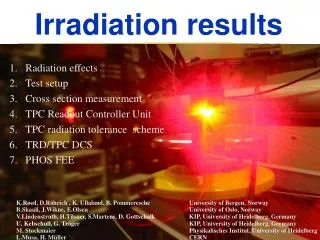
Preliminary L2 sensors irradiation results WBS 1.1.1. Regina Demina Kansas State University. Irradiation at KSU JRM. Facility: James R Macdonald lab at KSU 5-15 MeV proton beam Beam swept by electrostatic deflector for uniform irradiation can vary intensity to receive up to 1 Mrad/hour

E N D
Preliminary L2 sensors irradiation resultsWBS 1.1.1 Regina Demina Kansas State University
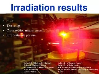
Irradiation at KSU JRM Facility: James R Macdonald lab at KSU • 5-15 MeV proton beam • Beam swept by electrostatic deflector for uniform irradiation • can vary intensity to receive up to 1 Mrad/hour • Sensors are held in vacuum chamber • Flux is measured by a Faraday cup. • Probing facility • Cold chuck – to 0oC Target chamber
Requirements for silicon sensors • Main challenge for silicon sensors - radiation • Depletion voltage (F) • Leakage current (F) noise • Doses comparable to LHC – use their R&D • NB: Uncertainty in F estimate– conservative approach 10 years of CMS at inner radius
L2 preliminary results For L2 20 fb-1 26 E12 1 Mev n/cm2 Point of inversion ~ 90 E12 n/cm2
L2 preliminary results For L2 20 fb-1 26 E12 1 Mev n/cm2 Alpha from this result ~1.2E-17A/cm, Frank used 3 in his estimates
Some break down seen after irradiation • Vbreak = ~550 V • After 1.2 E14 n/cm2
Summary • I don’t think we have any problems with L2 sensors
Spec L0, L1 Vbreak>700 V Spec L2-5 Vbreak>350 V Depletion voltage Specification on breakdown voltage derived based on depletion voltage evolution T=-10oC with warm up periods Hamburg model =20fb-1
Signal to noise ratio • Noise contributions: • Capacitive load: 450+43C(pF) • Al strip resistance + analogue cables (L0) • Shot noise Ileak=I0+aFAd (a=3E-17A/cm) • Thermal noise in Rbias Ileak=16mA/cm2 Goal: S/N> 10 Possible if T<-10oC for L0 and L1 T<-5oC for L2 – L5 Important to test Ileak after irradiation on prototype sensors and on test structures during production