Download
1 / 7
200 likes | 531 Vues
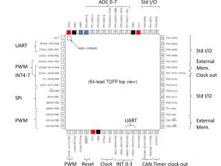
UART. Jin-Fu Li. Data Bit 7. Data Bit 4. Data Bit 3. Data Bit 2. Data Bit 6. Data Bit 5. Data Bit 1. Data Bit 0. Introduction. UART (modem) Universal asynchronous receiver and transmitter Data format. Serial Data Channel. Host processor 1. Host processor 2.

E N D
UART Jin-Fu Li
Data Bit 7 Data Bit 4 Data Bit 3 Data Bit 2 Data Bit 6 Data Bit 5 Data Bit 1 Data Bit 0 Introduction • UART (modem) • Universal asynchronous receiver and transmitter • Data format Serial Data Channel Host processor 1 Host processor 2 Modem Modem Stop Bit Start Bit Parity Bit EE613 VLSI Design
Block Diagram of a UART Rcv shtreg Serial in Rcv datareg Receiver controller Clock Generator Sys clock To host processor XMT datareg Load XMT Data reg Byte ready Transmitter controller T byte 1 1 Serial out XMT shfteg EE613 VLSI Design
UART – Transmitter Byte ready Load XMT shtreg Load XMT Datareg Transmitter data path controller Start Bit count Shift T byte Clear State Next state Byte ready: asserted by the host processor to indicate that data bus has valid data Load XMT Datareg: asserting transfers data bus to the transmitter data storage register, XMT datareg T byte: asserting initiates transmission of a byte of data, along with the stop, start, and parity bits Bit count: counts bits in the word during transmission State : state of the transmitter controller state machine Load XMT shtreg: asserting loads the contents of XMT datareg into XMT shtreg Start: signals the start of transmission Shift: directs XMT shtreg to shift by one bit toward the LSB and backfill with stop bit (1) Clear : clears bit counter Next state: the next state of the state machine controlling the data path of the transmitter EE613 VLSI Design
FSM State Diagram of Transmitter Byte ready==0 Idle Byte ready==1 Load XMT shtreg=1 T byte==0 waiting Start=0 Bit count ==word size +1 Start=1 T byte==1 Clear=1 sending Shift=1 EE613 VLSI Design
UART – Receiver Clr sample counter Read not ready in Inc sample counter Serial in Receiver data path controller Shift Sample counter load error1 Bit counter error2 State Next state Read not ready in: signals that the host is not ready to receive data Sample counter: counts the samples of a bit Bit counter: counts the bits that have been sampled State: state of the state machine controlling the data path of the receiver Clr sample counter: clear sample counter Clr bit counter: clear bit counter Shift: causes RCV shftreg to shift towards the LSB Load: causes RCV shftreg to transfer data to RCV datareg Error1: asserted if host is not ready to receive data after last bit has been sampled Error2: asserts if the stop-bit is missing Next state: next state of the state machine controlling the data path of the receiver EE613 VLSI Design
FSM State Diagram of Receiver Serial in==1 Idle Serial in==0 Load XMT shtreg=1 Serial in==1 Serial in==0 Sample counter 1=3 starting Inc sample counter=1 Clr sample counter=1 Serial in==0 Clear=1 Sample counter==3 receiving Inc sample counter=1 Sample counter 1=word size -1 EE613 VLSI Design