Download
1 / 17
180 likes | 406 Vues
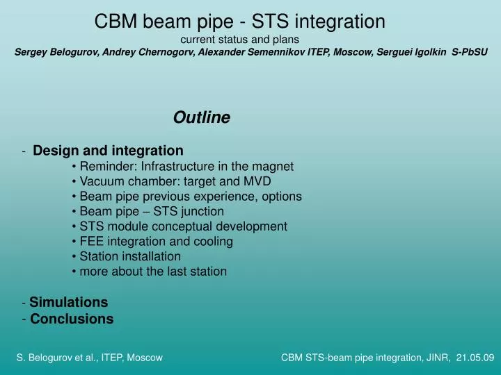
CBM beam pipe - STS integration current status and plans. Outline Design and integration Reminder: Infrastructure in the magnet Vacuum chamber: target and MVD Beam pipe previous experience, options Beam pipe – STS junction STS module conceptual development

E N D
CBM beam pipe - STS integration current status and plans • Outline • Design and integration • Reminder: Infrastructure in the magnet • Vacuum chamber: target and MVD • Beam pipe previous experience, options • Beam pipe – STS junction • STS module conceptual development • FEE integration and cooling • Station installation • more about the last station • Simulations • Conclusions Sergey Belogurov, Andrey Chernogorv, Alexander Semennikov ITEP, Moscow, Serguei Igolkin S-PbSU S. Belogurov et al., ITEP, Moscow CBM STS-beam pipe integration, JINR, 21.05.09
Reminder: Infrastructure in the magnet • Design from inside to outside (should be) • Power lines, data links, piping infrastructure are not under practical consideration yet. S. Belogurov et al., ITEP, Moscow CBM STS-beam pipe integration, JINR, 21.05.09
Vacuum chamber: target and MVD Target: (multiple or single layer) Reduce rescattering of heavy probes, narrow beam is needed Otherwise possible to spread the beam and separate tracks from simultaneous or closely pie-lapping events. Concerns also beam-pipe (later) MVD no layout available – affects design of the beampipe. S. Belogurov et al., ITEP, Moscow CBM STS-beam pipe integration, JINR, 21.05.09
Beam pipe: previous experience LHCb VELO 800 mm diam. 2 mm Al alloy, machined from a forged billet together with a bellow, NA61 – kevlar+mylar Добавить соображений S. Belogurov et al., ITEP, Moscow CBM STS-beam pipe integration, JINR, 21.05.09
Beam pipe: options We assume still that beampipe should be thin. The candidate material is Be. Can be easily machined down to 0.7 mm (~0.5 mm C) thickness, to 0.5 mm with an effort. For thinner objects foil is available. “NPO Kompozit” is interested to manufacture the scientific object for price close to net cost. Initially we consider the convex shape. At our thickness it should be mechanically stable. However we‘ll investigate also the concave option S. Belogurov et al., ITEP, Moscow CBM STS-beam pipe integration, JINR, 21.05.09
Beam pipe: options The problem of the stress release: bellows at the neck of the pipe, at the wide flange of the vacuum chamber, somewhere downstream; window 2x50 m – good also for the experiment reconfiguration. Open issue: stability of the window vs. width of the beam, anyway not worth than for the target. No radiation swelling at 1022 n/cm2 S. Belogurov et al., ITEP, Moscow CBM STS-beam pipe integration, JINR, 21.05.09
Beam pipe – STS junction FEA simulation of a cylinder for material budget minimization. Will be an open structure. Is it possible to have the single size of cylinder for all the station? Beampipe is anyway inside the 2.5 °. 8-th station 2.5 ° – 87 mm, max tube for the cylinder (middle rib not cut) is 56 mm. Seems yes, simulation is in progress. S. Belogurov et al., ITEP, Moscow CBM STS-beam pipe integration, JINR, 21.05.09
STS module conceptual development How to overlap sensors, how to cool them (gas or tubes)? Gas cooling – small material, low temperature (evaporated LN2 – no hail). A lot of tricky mylar foils for correct flux organization, tubes are more easy. S. Belogurov et al., ITEP, Moscow CBM STS-beam pipe integration, JINR, 21.05.09
FEE integration and cooling Soldered tubes and plate or milled groove with compound Ruby ball for torque less fixation. Thermal contact of FEB to heatsink S. Belogurov et al., ITEP, Moscow CBM STS-beam pipe integration, JINR, 21.05.09
Station installation Note big additional height due to current mechanics. Approximation to 8-th station ~1600 mm (1). What can be reduced – cable between FEB and the last sensor; height of the heat sink; S. Belogurov et al., ITEP, Moscow CBM STS-beam pipe integration, JINR, 21.05.09
Station installation into mainframe Linear bearing NB SEBS-15BYM-UU-2-T1-430-P-W2 S. Belogurov et al., ITEP, Moscow CBM STS-beam pipe integration, JINR, 21.05.09
Station installation Height for the price of width. Gap of 1400 mm seems comfortable for mechanics. Possibility to match 1300 mm will be studied. Note. For the first 2 or 3 stations another kind of support should probably be developed S. Belogurov et al., ITEP, Moscow CBM STS-beam pipe integration, JINR, 21.05.09
more about the last station It was discussed by Iouri: for operation without MVD, even for primary vertex localization, one may need better vertical resolution. May be achieved by rotating some (e.g. the first and the last) of the stations by 90° – the answer: concerning mechanics – no problem. Existing type of ladders may be used S. Belogurov et al., ITEP, Moscow CBM STS-beam pipe integration, JINR, 21.05.09
Simulations First exercise with cbmroot. Look at hit density for several beampipes. 25 AGeV central UrQMD. // description of shape PCON: // - material // - number of points // - azimuthal angle from xxx to yyy [deg] // - point 1: z inner-radius outer-radius [mm] ... PCON carbon 6 0. 360. -50. 25. 25.5 25. 25. 25.5 35. 130. 130.5 240. 130. 130.5 270. 10. 10.5 1600. 32. 32.5 “thin” window vs. “normal” window S. Belogurov et al., ITEP, Moscow CBM STS-beam pipe integration, JINR, 21.05.09
Station Window A kind of figure of merit is desirable for design. Try to understand better the tracking algorithm Average dist. ~ 1/√ (hit density); 4 cm-2 → 5 mm S. Belogurov et al., ITEP, Moscow CBM STS-beam pipe integration, JINR, 21.05.09
Thin window Normal window Simulations Look at hit density in “square” rings vs. beampipe configuration. Results (higher effects at bigger radii) are not obvious at fingertips – to be checked carefully, may be soft deltas in the field? S. Belogurov et al., ITEP, Moscow CBM STS-beam pipe integration, JINR, 21.05.09
Conclusions • There is a temptation to build a cheap and thick beam pipe. To be carefully studied in order to avoid late vain regrets. • Beam pipe design depends on MVD. Too early for fixing. However design of junction between beam pipe and STS seems to be understood. • For choosing the sensors cooling method one has to evaluate the negative effect of the tubes with cooling liquid along the ladders. Liquid cooling is much easier than the gas one. • What is the profit in the STS physical performance due to current positioning of the stations in comparison to uniform one (each 10 cm). Is current positioning optimal? 7-th and 8-th station can’t be placed closer than 10 cm to each other without a big effort, is it acceptable? • If necessary, concerning mechanics, modules can be mounted horizontally. • Current understanding of the STS mechanics require a magnet gap of 1400 mm, we’ll try to match 1300 mm. Is it possible to evaluate price and field “quality” for both otions? S. Belogurov et al., ITEP, Moscow CBM STS-beam pipe integration, JINR, 21.05.09