Download
1 / 186
1.94k likes | 2.3k Vues
Database Theory. Jason Fan. Outline. Basic Concepts Database and Database Users (Chapter 1) Database System Concepts and Architecture (Chapter 2) Database Design Database Design Process (Chapter 16) Entity-Relationship (ER) Modeling (Chapter3)

E N D
Database Theory Jason Fan
Outline • Basic Concepts • Database and Database Users (Chapter 1) • Database System Concepts and Architecture (Chapter 2) • Database Design • Database Design Process (Chapter 16) • Entity-Relationship (ER) Modeling (Chapter3) • Functional Dependencies and Normalization for Relational Database (Chapter 14) • Relational Design Algorithms (Chapter 15) • Relational Data Model Mapping (Chapter 9) • Relational Database • The Relational Data Model (Chapter 7) • Relational Algebra (Chapter 7) • SQL – A Relational Database Language (Chapter 8) • Relational Calculus (Chapter 9) • Database Implementation • Transaction Processing (Chapter 19) • Concurrency Control (Chapter 20) • Database Recovery (Chapter 21) • Advanced Topics
Database and Database Users • Basic Concepts • Main Characteristics of Database Technology • Classes of Database Users • Additional Database Characteristics • When not to use a DBMS Chapter 1 Database and Database Users
Basic Concepts • Database A collection of related data. • Data Known facts that can be recorded and have implicit meaning. • Mini-world Some part of the real world about which data is stored in database. • Database Management System (DBMS) A software package to facilitate the creation and maintenance of a computerized database. • Database System The DBMS software together with the data itself. Chapter 1 Database and Database Users
Main Characteristics of Database Technology • Self-contained nature of a database system A DBMS catalog stores the description (meta-data) of the database. This allows the DBMS software to work with different databases. • Insulations between program and data • Data abstractions A data model is used to hide storage details and present the user with a conceptual view of the database. • Program-data independence Allows changing data storage structures without having to change the DBMS access programs. • Program-operation independence Allows changing operation implementation without having to change the DBMS access programs. • Support of multiple views of data Chapter 1 Database and Database Users
Additional Characteristics of Database Technology • Controlling data redundancy • Restricting unauthorized access to data. • Providing persistent storage for program objects and data structure. • Providing multiple interfaces to different classes of users. • Representing complex relationships among data. • Enforcing integrity constraints on the database. • Providing backup and recovery services. • Potential for enforcing standards. • Flexibility to change data structures. • Reduced application development time. • Availability of up-to-date information. • Economies of scale. Chapter 1 Database and Database Users
Classes of Database Users • Workers on the scene : Persons whose job involves daily use of a large database. • Database administrators (DBAs): Responsible for managing the database system. • Database designers : Responsible for designing the database. • End users : Access the database for querying , updating , generating reports, etc. • Casual end users : Occasional users. • Parametric (or naive) end users : They use pre-programmed canned transactions to interact continuously with the database. For example, bank tellers or reservation clerks. • Sophisticated end users : Use full DBMS capabilities for implementing complex applications. • System Analysts/Application programmers : Design and implement canned transactions for Parametric users. • Workers behind the scene: Persons whose job involves design , development , operation, and maintenance of theDBMS software and system environment. • DBMS designers and implementers : Design and implement the DBMS software package itself. • Tool developers : Design and implement tools that facilitate the use of DBMS software. Tools include design tools , performance tools , special interfaces , etc. • Operators and maintenance personnel : Work on running and maintaining the hardware and software environment for the database system. Chapter 1 Database and Database Users
When not to Use a DBMS • Main costs of using a DBMS • High initial investment and possible need for additional hardware. • Overhead for providing generality, security, recovery, integrity, and concurrency control. • When DBMS may be unnecessary: • If the database and applications are simple, well defined and not expected to change. • If there are stringent real-time requirements that may not be met because of the DBMS overhead • If access to data by multiple users is not required. Chapter 1 Database and Database Users
Database System Concepts and Architecture • Data Models • Three-Schema Architecture • Data Independence • DBMS Languages • DBMS Interfaces • DBMS Architecture • Database System Utilities • Classification of DBMS Chapter 2 Database Concepts and Atchitecture
Data Models • Data Model A set of concepts to describe the structure of a database, and certain constraints that the database should obey. • Data Model Operations Operations for specifying database retrievals and updates by referring to the concepts of data model. • Categories of data models • Conceptual (high-level, semantic) data models: Provide concepts that are close to the way many users perceive data. (Also called entity-based or object-based data models) • Physical (low-level, internal) data models: Provide concepts that describe the details of how data is stored in the computer. • Implementation (record-oriented) data models: Provide concepts that fall between above two, balancing user views with some computer storage details. Chapter 2 Database Concepts and Atchitecture
Data Models • Database Schema The description of database. Includes description of database structure and the constraints that should hold on the database. • Database catalog Stores database schema. • Schema Diagram A diagrammatic display of ( some aspects of) a database schema. • Database Instance The actual data stored in a database at a particular moment in time. Also called database state (or occurrence) • The database schema changes very infrequently. The database state changes every time the database is updated. Schema is also called intension, whereas the state is called extension. Chapter 2 Database Concepts and Atchitecture
Three Schema Architecture • Internal schema at the internal level to describe data storage structures and access paths. Typically uses a physical data model. • Conceptual schema at the conceptual level to describe the structure and constraints for the whole database. Uses a conceptual or an implementation data model . • External schemas at the external level to describe the various user views. Usually uses the same data model as the conceptual level. • Mappings transform requests and results between levels. Chapter 2 Database Concepts and Atchitecture
Database System Architecture External View External View External Level external/conceptual mapping Conceptual Level Conceptual Schema conceptual/internal Mapping Internal Level Internal Schema Stored Databases Chapter 2 Database Concepts and Atchitecture
Data Independence • Logical Data Independence The capacity to change the conceptual schema without having to change the external schemas and their application programs. • Physical Data Independence The capacity to change the internal schema without having to change the conceptual schema. • When a schema at a lower level is changed, only the mappings between this schema and higher level schemas need to be changed in a DBMS that fully supports data independence. • Mappings create overhead Chapter 2 Database Concepts and Atchitecture
Database System Languages • Data Definition Language (DDL) Used by the DBA and database designers to specify the conceptual schema of a database. In many DBMSs, the DDL is also used to define internal and external schemas(views). In some DBMSs, separate storage definition language (SDL) and view definition language (VDL) are used to define internal and external schemas. • Data Manipulation Language (DML) Used to specify database retrievals and updates. • High-level (nonprocedural) DML can be used on its own to specify database operations. • Low-level (procedural) DML retrieves a record at a time and must be embedded in a general-purpose programming language. • When DML is embedded in a general-purpose programming language (host language), it is called data sublanguage. • When DML is used in a stand-alone interactive manner, it is called query language Chapter 2 Database Concepts and Atchitecture
DBMS Interfaces • Stand-alone query language interfaces. • Programmer interfaces for embedding DML in programming languages: • Pre-compiler Approach • Procedure (Subroutine) Call Approach • Menu-based • Graphic-based • Forms-based • Natural language • Combination of above • Parametric interfaces using function keys • Report generation languages • Interfaces for DBA: • Creating accounts, granting authorizations • Setting system parameters • Changing schemas or access path Chapter 2 Database Concepts and Atchitecture
Database System Utilities • Loading data stored in files into a database. • Backing up the database periodically on tape. • Reorganizing database file structures. • Generating Report. • Performance monitoring. • Sorting files. • User monitoring. • Data compression. Chapter 2 Database Concepts and Atchitecture
Classification of DBMSs • Based on the data model used: • Relational • Multidimensional • Network • Hierarchical. • Object-oriented • Semantic • Entity-Relationship • Other Classifications: • Single-user vs. multi-user • Centralized vs. distributed • Homogeneous vs. Heterogeneous • OLTP vs. OLAP Chapter 2 Database Concepts and Atchitecture
Database Design • Goals of Database Design • Satisfy the information content requirements of the specified users and applications • Provide natural and easy-to-understand structuring of information • Support processing requirements and any performance objectives • Database Design Process • Requirement collection and analysis • Conceptual database design • Choice of DBMS • Data model mapping (Logical database design) • Physical database design • Database system implementation and tuning Chapter 16 Practical Database Design and Tuning
Requirement Collection and Analysis • The major application areas and user groups that will use the database or whose work will be affected by it are identified. Key individuals and committees within each group are chosen to carry out subsequent steps of requirement analysis • Existing documentations concerning the applications is studied and analyzed. • The current operating environment and planned use of the information is studied. • Written responses to sets of questions are sometimes collected from potential users or user groups. Key individuals may be interviewed to help in assessing the worth of information and in setting up of priorities. Chapter 16 Practical Database Design and Tuning
Conceptual Database Design • Conceptual Schema Design • Choice of high-level conceptual data model such as ER model and dimensional model • Approaches to conceptual schema design • centralized schema design approach • view integration approach • Strategies for conceptual schema design • top-down strategy • bottom-up strategy • inside-out strategy • mixed strategy • Transaction Design Chapter 16 Practical Database Design and Tuning
Physical Database Design • Criteria for guiding the physical database design • Response time • Space utilization • Transaction throughput • Physical database design in relational database • Factors that influent the physical database design • Analyzing the database queries and transactions • Analyzing the expected frequencies of invocation of queries and transactions • Analyzing the time constraints for queries and transactions • Analyzing the expected frequencies of update operations • Analyzing the uniqueness constraints on attributes • Physical database design decisions • Indexing • De-normalization • Storage design Chapter 16 Practical Database Design and Tuning
Database Tuning in Relational Database • Goals • Make application run fast • lower the response time of queries and transactions • improve the overall throughput of transactions • Tuning indexes • Some queries may take too long for lack of an index • Some indexes may not get utilized • Some indexes may causing excessive overhead • Tuning database design • De-normalization • Table partition • Duplicate attributes • Tuning queries Chapter 16 Practical Database Design and Tuning
Automated Design Tools • Database Design Tools • Erwin • Rational Rose • Power Designer • Schema Diagram Notation • UML (Unified Modeling Language) • IDEF1X (Integration Definition for Information Modeling) • IE (Information Engineering) • CHEN's ERD Notation Chapter 16 Practical Database Design and Tuning
Entity-Relationship (ER) Modeling • Example Database Application (COMPANY) • ER Model Concepts • Entities and Attributes • Entity Types, Value Sets, and Key Attributes • Relationships and Relationship Types • Structural Constraints and Roles • Weak Entity Types • ER Diagrams Notation • Relationships of Higher Degree • Enhanced ER Modeling Chapter 3 Data Modeling Using the Entity-Relationship Model
Example of COMPANY Database • Requirements for the COMPANY Database: • The company is organized into departments. Each department has a name, number, and a employee who manages the department. We keep track of the start date of the department manager. A department may have several locations. • Each department controls a number of projects. Each project has a name, number, and is located at a single location. • We store each employee's social security number, address, salary, sex and birth date. Each employee works for one department but may work on several projects. We keep track of the number of hours per week that an employee currently works on each project. We also keep track of the direct supervisor of each employee. • each employee may have a number of dependents. For each dependent, we keep their name, sex, birth date, and relationship to the employee. Chapter 3 Data Modeling Using the Entity-Relationship Model
ER Model Concepts: Entities and Attributes • Entities Entities are specific objects orthings in the mini-world that are represented in the database; for example, the EMPLOYEE John Smith, the Research DEPARTMENT, the ProductX PROJECT. • Attributes Attributes are properties used to describe an entity; for example, an EMPLOYEE entity may have a Name, SSN, Address, Sex, BirthDate. A specific entity will have a value for each of its attributes; for example a specific employee entity may have Name = 'John Smith', SSN = '123456789', Address = '731 Fondren , Houston, TX', Sex = 'M', BirthDate = '09-JAN-55'. • Attribute Types • Simple: each entity has a single atomic value for the attribute; for example SSN or Sex. • Composite: Attribute may be composed of several components; for example Name(FirstName, MiddleName, LastName). Composition may form a hierarchy where some components are themselves composite. • Multi-Valued: An entity may have multiple values for that attribute; for example Color of a CAR or PreviousDegrees of a STUDENT. Denoted as {Color} or { PreviousDegrees}. Chapter 3 Data Modeling Using the Entity-Relationship Model
ER Model Concept: Entity Types and Key Attributes • Entity Type Entity type defines a set of entities that have the same attributes. For example, the EMPLOYEE entity type or the PROJECT entity type. • Key Attribute An attribute of an entity type for which each entity must have a unique value is called a key attribute of the entity type. For example, SSN of EMPLOYEE. • A key attribute may be composite. For example, VehicleRegistrationNumber is a key of the CAR entity type with components(Number, State). • An entity type may have more than one key. For example, the CAR entity type may have two keys: VehicleIdentificationNumber and VehicleRegistrationNumber(Number, State). • Domains (Value Sets) of Attributes Each simple attribute of an entity type is associates with a domain, which specifies the set of values the may be assigned to that attribute for each individual entity. Chapter 3 Data Modeling Using the Entity-Relationship Model
ER Model Concepts: Relationships and Relationship Types • Relationship A relationship relates two or more distinct entities with a specific meaning; for example, EMPLOYEE John Smith works on the ProductX PROJECT or EMPLOYEE Franklin Wong manages the Research DEPARTMENT. • Relationship Type Relationship of the same type are grouped or typed into a relationship type. For example, the WORKS_ON relationship type in which EMPLOYEEs and PROJECTs participate, or the MANAGEs relationship type in which EMPLOYEEs and DEPARTMENTs participate. More than one relationship type can exist with the same participating entity types; for example, MANAGES and WORKS_FOR are distinct relationships between EMPLOYEE and DEPARTMENT participate. • The degree of a relationship type The degree of a relationship type is the number of participating entity types. binary relationships, ternary relationship, n-ary relationship Chapter 3 Data Modeling Using the Entity-Relationship Model
ER Model Concepts: Structural Constraints and roles • A relationship can relate two entities of the same entity type; for example, a SUPERVISION relationship type relates one EMPLOYEE ( in the role of supervisee) to another EMPLOYEE ( in the role of supervisor). This is called a recursive relationship type. • A relationship type can have attributes; for example, HoursPerWeek of WORKS_ON; its value for each relationship instance describes the number of hours per week that an EMPLOYEE works on a PROJECT. • Structural constraints on relationships • Cardinality ratio ( of a binary relationship): 1:1, 1:N, N:1, or M:N. • Participation constraint (on each participating entity type): total (called existence dependency) or partial. Chapter 3 Data Modeling Using the Entity-Relationship Model
ER Model Concepts: Weak Entity Types • An entity type that does not have a key attribute • A weak entity type must participate in an identifying relationship type with an owner or identifying entity type • Entities are identified by the combination of a partial key of the weak entity type and the key of the identifying entity type. • Example Suppose that a DEPENDENT entity is identified by the dependent’s first name and birth date, and the specific EMPLOYEE that the dependent is related to. DEPENDENT is a weak entity type with EMPLOYEE as its identifying entity type via the identifying relationship type DEPENDENT_OF. Chapter 3 Data Modeling Using the Entity-Relationship Model
Conceptual Design of COMPANY Database • Entity types • DEPARTMENT • PROJECT • EMPLOYEE • DEPENDENT • Relationship types • Manage (1:1) • Work_for (1:n) • Supervision (1:n) • Controls (1:n) • Works_on (m:n) • Has_dependent (1:n) Chapter 3 Data Modeling Using the Entity-Relationship Model
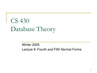
Number Fname Minit Lname Address Location Name Works_for Name Name N 1 SSN Sex DEPARTMENT Bdate EMPLOYEE Manages 1 1 Supervision StartDate 1 1 Controls Works_on N N M N Hours PROJECT DEPENDENT 1 Has_dependents Number Name Relationship Name Bdate Sex Location N ER Diagram of COMPANY Database Chapter 3 Data Modeling Using the Entity-Relationship Model
Alternative Notation for Relationship Structural Constraints • Specified on each participation of an entity type E in a relationship type R. • Specifies that each entity e in E participates in at least min and at most max relationship instances in R. • Default(no constraint): min = 0, max = n. • Must have min max, min 0, max 1. • Examples • A department has exactly one manager and an employee can manage at most one department. • Specify (1,1) for participation of DEPARTMENT in MANAGES • Specify (0,1) for participation of EMPLOYEE in MANAGES • An employee can work for exactly one department but a department can have any number of employees. • Specify (1,1) for participation of EMPLOYEE in WORKS_FOR • Specify (0,n) for participation of DEPARTMENT in WORKS_FOR Chapter 3 Data Modeling Using the Entity-Relationship Model
Number Fname Minit Lname Address Location Name Name Name SSN Sex DEPARTMENT Bdate EMPLOYEE Supervision 1 1 Controls Works_on N N M N Hours PROJECT DEPENDENT 1 Has_dependents Number Name Relationship Name Bdate Sex Location N ER Diagram of COMPANY Database Works_for 0:N 1:1 Manages 1:1 0:1 StartDate Chapter 3 Data Modeling Using the Entity-Relationship Model
Enhanced Entity-Relationship and Object Modeling • Subclass, Superclass and Inheritance • Specialization and Generalization • Disjoin/Overlapping • Total/Partial • Union/Categories Chapter 4 Enhanced Entity-Relationship and Object Modeling
The Relational Data Model • Relational Model Concepts • Characteristics of Relations • Relational Integrity Constraints • Domain Constraints • Key Constraints • Entity Integrity Constraints • Referential Integrity Constraints • Update Operations on Relations Chapter 7 The Relational Data Model, Relational Constraints, and the Relational Algebra
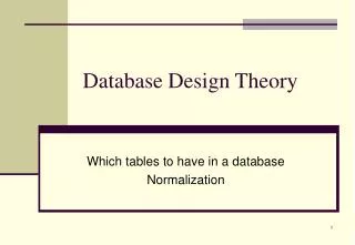
Attributes Relation name PRODUCT ProductID ProductName UnitPrice UnitInStock Tuples ORDER_ITEM OrderID ProductID Quantity Discount UnitPrice 20.00 25.00 18.00 22.00 21.00 1 3 2 2 3 1 1 11 11 1 11 1 Queso Cabrales Chai Aniseed Syrup 3 21.00 20 30 15 35 22.00 18.00 10 0.2 22 53 0.2 0.15 39 0.1 0.1 Relational Model Concepts Chapter 7 The Relational Data Model, Relational Constraints, and the Relational Algebra
Relational Model Concepts • Relation ( informally). A table of values. Each column in the table has a column header called an attribute. Each row is called a tuple. • Formal relational concepts. • Domain: A set of atomic (indivisible) values. • Attribute: A name to suggest the meaning that a domain plays in a particular relation. Each attribute Ai has a domain Dom(Ai). • Relation schema: A relation name R and a set of attributes Ai that define the relation. Denoted by R(A1, A2, ... ,an). For example: student(name, SSN, BirthDate, Addr). • Relational Database Schema: A set S of relation schemas that belong to the same database. S is thename of the database. S = {R1, R2, ...,Rn}. • Degree of a relation: its number of attributes n. • Tuple t of R(A1, A2,....,An): a (ordered) set of values t = < v1, v2, ..., vn> where each value vi is an element of Dom(Ai). Also called a n-tuple. • Relation instance r(r): A set of tuples r(r) = {t1, t2,...,Tm}, or alternatively r(r) dom(a1) dom(a2) ... dom(an). Chapter 7 The Relational Data Model, Relational Constraints, and the Relational Algebra
Characteristics of Relations • The tuples are not considered to be ordered, even though they appear to be in the tabular form. • We will consider the attributes in R(A1, A2, ...,An) and the values in t = < v1, v2, .., vn> to be orderd.( However, a more general alternative definition of relation does not require this ordering). • All values are considered atomic (indivisible). A special null value is used to represent values that are unknown or inapplicable to certain tuples. • Notation • We refer to component values of a tuple t by t[Ai] = vi (the value of attribute Ai for tuple t) • Similarly, t[Au, Av, ..., Aw] refer to the sub-tuple of t containing the values of attributes Au, Av, ..., Aw, respectively. Chapter 7 The Relational Data Model, Relational Constraints, and the Relational Algebra
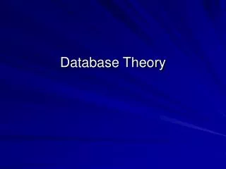
Primary key Attributes Relation name PRODUCT ProductID ProductName UnitPrice UnitInStock Tuples Primary key Foreign key ORDER_ITEM OrderID ProductID Quantity Discount UnitPrice 20.00 25.00 18.00 22.00 20.00 1 1 2 1 2 3 3 11 11 1 11 Chai Queso Cabrales 3 1 Aniseed Syrup 20 15 30 30 21.00 18.00 22.00 10 39 0.2 0.2 53 0.1 0.1 22 0.15 Relational Constraints Chapter 7 The Relational Data Model, Relational Constraints, and the Relational Algebra
Relational Constraints • Constraints are conditions that must hold on all valid relation instances. There are three main types of constraints: • Domain Constraints Values of each attribute must be atomic. • Key Constraints • Superkey of R: A set of attributes SK of R such that no two tuples in any valid relation instance r(R) will have the same value for SK. That is, for any distinct tuples t1 and t2 in r(R), t1[SK] t2[SK] • Key (candidate key) of R: A “minimal” superkey; that is, a superkey K such that removal of any attribute form K results in a set of attributes that is not a superkey. • Example: The CAR relation schema: CAR(State, Reg#, SerialNo, make, Model, Year) has two keys: Key1 = {State, Reg#}, Key2 {SerialNo}; which are also superkeys. {SerialNo, Make} is a superkey but not a key. • If a relation has several candidate keys, one is chosen arbitrarily to be the primary key. The primary key attributes are underlined. Chapter 7 The Relational Data Model, Relational Constraints, and the Relational Algebra
Relational Constraints • Entity Integrity The primary key attributes PK of each relation schema R in S can not have null values in any tuple of r(R). This is because primary key values are used to identify the individual tuples. t[PK] null for any tuple t in r(R). • Referential Integrity Referential integrity constraint is used to specify a relationship among tuples in two relations: the referencing relation and referenced relation. It involves two relations. Tuples in the referencing relation R1 have attributes FK (called foreign key attributes) that reference the primary key attributes PK of the referenced relation R2. A tuple t1 in R1 is said to reference a tuple t2 in R2 if t1[FK] = t2 [PK]. A referential integrity constraint can be displayed in a relational database schema as a directed arc from R1.FK to R2. Chapter 7 The Relational Data Model, Relational Constraints, and the Relational Algebra
Attributes Relation name PRODUCT ProductID ProductName UnitPrice UnitInStock Tuples 13 13 xyz Syrup 23.00 22.00, 21.00 25, 35 20 ORDER_ITEM OrderID ProductID Quantity Discount UnitPrice 21.00 3 1 11 2 1 1 2 3 11 1 11 3 Chai Aniseed Syrup Queso Cabrales 1 15 10 35 20 22.00 18.00 30 21.00 0.2 39 0.1 53 22 0.15 0.1 0.2 Operations 20.00 25.00 18.00 22.00 Chapter 7 The Relational Data Model, Relational Constraints, and the Relational Algebra
Update Operations on Relations • Update Operations • INSERT a tuple • DELETE a tuple • MODIFY a tuple • Integrity constraints should not be violated by the update operations. • Insert operation could violate any constraint. • Delete operation could violate referential constraints. • Modify a primary key or foreign key attribute is equivalent to delete one tuple and insert another. Modify other attributes cause no problems. • Several update operations may have to be grouped together. • Updates may propagate to cause other updates automatically. This may be necessary to maintain integrity constraints. • In case of integrity violation, several actions can be taken: • cancel the operation that causes the violation • perform the operation but inform the user of violation • trigger additional updates so the violation is corrected • execute a user-specified error-correction routine Chapter 7 The Relational Data Model, Relational Constraints, and the Relational Algebra
Data Model Mapping • ER-to-Relational Mapping • EER-to-Relational Mapping Capter 9 ER- and EER-to-Relational Mapping, and Other Relational Languages
EMPLOYEE FNAME MINIT LNAME SSN BDATE ADDRESS SEX SALARY SUPERSSN DNO DEPARTMENT DNAME DNUMBER MGRSSN MGRSTARTDATE DEPT_LOCATION DNUMBER DLOCATION PROJECT PNAME PNUMBER PLOCATION DNUM WORKS_ON ESSN PNO HOURS DEPENDENT ESSN DEPENDENT_NAME SEX BDATE RELATIONSHIP Relational Model of COMPANY Database Capter 9 ER- and EER-to-Relational Mapping, and Other Relational Languages
ER-to-Relational Mapping • STEP 1: For each regular (strong) entity type E in the ER schema, create a relation R that includes all the simple attributes of E. Include only the simple component attributes of a composite attribute. Choose one of the key attributes of E as primary key for R. If the chosen key of E is composite, the set of simple attributes that form it will together form the primary key of R. • STEP 2: For each weak entity type W in the ER schema with owner entity type E, create a relation R, and include all simple attributes (or simple components of composite attributes) of W as attributes of R. In addition, include as foreign key attributes of R the primary key attribute(s) of the relation(s) that correspond to the owner entity type(s); this takes care of the identifying relationship type of W. The primary key of R is the combination of the primary key(s) of the owner(s) and the partial key of the weak entity type W, if any. • STEP 3: For each binary 1:1 relationship type R in the ER schema, identify the relations S and T that correspond to the entity types participating in R. Choose one of the relations—S, say—and include as foreign key in S the primary key of T. It is better to choose an entity type with total participation in R in the role of S. Include all the simple attributes (or simple components of composite attributes) of the 1:1 relationship type R as attributes of S. • STEP 4: For each regular binary 1:N relationship type R, identify the relation S that represents the participating entity type at the N-side of the relationship type. Include as foreign key in S the primary key of the relation T that represents the other entity type participating in R. Include any simple attributes (or simple components of composite attributes) of the 1:N relationship type as attributes of S. Capter 9 ER- and EER-to-Relational Mapping, and Other Relational Languages
ER-to-Relational Mapping • STEP 5: For each binary M:N relationship type R, create a new relation S to represent R. Include as foreign key attributes in S the primary keys of the relations that represent the participating entity types; their combination will form the primary key of S. Also include any simple attributes of the M:N relationship type (or simple components of composite attributes) as attributes of S. Notice that we cannot represent an M:N relationship type by a single foreign key attribute in one of the participating relations—as we did for 1:1 or 1:N relationship types—because of the M:N cardinality ratio. • STEP 6: For each multivalued attribute A, create a new relation R. This relation R will include an attribute corresponding to A, plus the primary key attribute K—as a foreign key in R—of the relation that represents the entity type or relationship type that has A as an attribute. The primary key of R is the combination of A and K. If the multivalued attribute is composite, we include its simple components. • STEP 7: For each n-ary relationship type R, where n > 2, create a new relation S to represent R. Include as foreign key attributes in S the primary keys of the relations that represent the participating entity types. Also include any simple attributes of the n-ary relationship type (or simple components of composite attributes) as attributes of S. The primary key of S is usually a combination of all the foreign keys that reference the relations representing the participating entity types. However, if the cardinality constraints on any of the entity types E participating in R is 1, then the primary key of S should not include the foreign key attribute that references the relation E’ corresponding to E. This concludes the mapping procedure. Capter 9 ER- and EER-to-Relational Mapping, and Other Relational Languages
EER-to-Relational Mapping • STEP 8: Convert each specialization with m subclasses {S1, S2, . . ., Sm} and (generalized) superclass C, where the attributes of C are {k, a1, . . ., an} and k is the (primary) key, into relation schemas using one of the four following options: • Option 8A: Create a relation L for C with attributes Attrs(L) = {k, a1, . . ., an} and PK(L) = k. Create a relation Li for each subclass Si, 1 1 i 1 m, with the attributes Attrs(Li) = {k}D {attributes of Si} and PK(Li) = k. • Option 8B: Create a relation Li for each subclass Si, 1 1 i 1 m, with the attributes Attrs(Li) = {attributes of Si}D {k, a1, . . ., an} and PK(Li) = k. • Option 8C: Create a single relation L with attributes Attrs(L) = {k, a1, . . ., an} D {attributes of S1} D . . . D {attributes of Sm} D {t} and PK(L) = k. This option is for a specialization whose subclasses are disjoint, and t is a type (or discriminating) attribute that indicates the subclass to which each tuple belongs, if any. This option has the potential for generating a large number of null values. • Option 8D: Create a single relation schema L with attributes Attrs(L) = {k, a1, . . ., an} D {attributes of S1} D . . . D {attributes of Sm} D {t1, t2, . . ., tm} and PK(L) = k. This option is for a specialization whose subclasses are overlapping (but will also work for a disjoint specialization), and each ti, 1 1 i 1 m, is a Boolean attribute indicating whether a tuple belongs to subclass Si. Capter 9 ER- and EER-to-Relational Mapping, and Other Relational Languages