Download
1 / 28
280 likes | 438 Vues
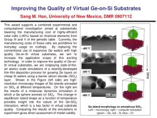
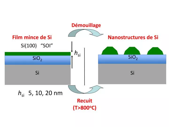
Démouillage. Film mince de Si. Nanostructures de Si. SiO 2. Si. Recuit (T>800 o C). Si(100) “SOI”. h si. SiO 2. Si. h si 5, 10, 20 nm. <130>. The end product: nanoislands are semi-organized. (100). (130). (150). (150). (100). (150). (130). (100). 10 μ m.

E N D
Démouillage Film mince de Si Nanostructures de Si SiO2 Si Recuit (T>800oC) Si(100) “SOI” hsi SiO2 Si hsi 5, 10, 20 nm
<130> The end product: nanoislands are semi-organized (100) (130) (150) (150) (100) (150) (130) (100) 10 μm
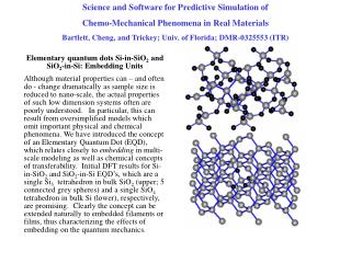
Surface energy driven kinetics of SOI dewetting LEEM / KMC A~t0.5 (Srolovitz et al. JAP, 1986) A (μm2) Area (μm2) A~t0.8 (Wong et al. Acta Mat., 2000) t (arb. unit) t (s) Kinetic Monte Carlo simulations LEEM • SOS square lattice (3ML thick film) Si(001) Surface Energy driven • T=860°C • First neighbors interaction • H=21±2 nm • Substate/Film interaction • Diffusion limited kinetics Continuum models Nucleation on facet based model A~t(Pierre-Louis et al., PRL, 2009)
Front velocity anisotropy versus local rim height 32±3 nm 29±3 nm Map of front position versus time (LEEM) Rim height (AFM) • Rim centers thicken and slow down (v ~ t-0.5) • Void fingers exhibit constant velocity Void fingers have constant rim height
Steady state dewetting of <110> front The <110> front velocity is stable and fingers are organized <110> Vfront = 49±2 nm/s (T=900°C)
AFM versus KMC at the void finger tip AFM KMC Height (ML) z (μm) x (atomic unit) x (μm)
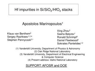
Receeding front J B Si film h A J=-D.grad (c) L SiO2 Es/kTh ceq,A≈ ceq,Be Es/kTh DΩ ceq,B (e -1) Vfinger~ hL Finger void velocity model/experiment Side view Top view Accumulated Si Si rim Si film ceq,A> ceq,B B A Void finger Receeding front 12nm 6nm 6 nm 8nm h=21nm Danielson PhD (MIT, USA) 21 nm Es: adsorbate-substrate excess energy
The thermal activation barrier to dewet Receeding front J B Si film h A L SiO2 Side view Top view Void finger speed Accumulated Si Si rim ceq,A> ceq,B Si film B A Void finger Receeding front Ea=2.0±0.2 eV Barrier surface smoothing on Si(100): Ea=2.3±0.1 eV (T=800-1100oC)* Void fingers *M.E. Keeffe, J. Phys. Chem. Solids (1994) Es: adsorbate-substrate excess energy Ea: activation energy
Dynamics of solid state dewetting: straight fronts a model system for dewetting
<110>- and <100>- Si/SiO2 straight fronts H=21 nm; T=804oC (84.7 min) Lithography e- LEEM <100> (Plateforme Planete C’Nano PACA) Unstable front 500 m Optical Microscopy 15 µm Atomic Force Microscopy <110> <110> 60 m Cheynis et al., accepted PRB 2011 <100> 1D profile Stable front Z (m) 5 m 0 0.18 m 7 m -0.2 7 m
Stable front: evidence of a facetted rim in situ LEEM Si rim SiO2 Rim profile of stable front is facetted 15 µm • Experiment: • exp=0.35±0.05 • Theory: • theory=7/220.32 • Pierre-Louis et al. PRL 2009 • Dufay et al. PRL 2011 =0.38±0.05 T=970°C Rim displacement:xt Si =0.31±0.05 Si T=825°C • Leroy et al. En preparation
0s 1250s 4 µm Aire (μm2) t (s)
Aire (μm2) t (arb. unit)
Height (ML) z (μm) x (μm) x (unité atomique)
Vue de dessus Vue de côté Recul du front Si accumulé Bourrelet de Si J ceq,A> ceq,B B B A h A Film de Si Void finger L Film de Si SiO2 Recul du front
Lithographie Microscopie Optique PMMA Si SiO2 Si (wafer) faisceau e- 500 m Microscopie à force atomique Gravure du Si 1D profile Z (m) 5 m 0 « Lift off » 0.18 m 7 m -0.2 <110> 60 m 7 m <100>
4 µm trou carré doigt nanostructure
Nucléation hétérogène fronts <110> Tranchée Film de Si démouillé Film de Si 5 µm 0 min 140 µm Front stable <110> 530 µm Front instable <100> 100 µm 670 µm 24 min
3 2 Déplacement du front (µm) 1 0 0 20 40 60 temps (min) x =0.38±0.05 T=970°C =0.31±0.05 T=825°C t
<100> Bourrelet de Si SiO2 <110> 15 µm
<100> Bourrelet de Si 15 µm SiO2 <110> 1 200 Croissance (couche/couche) 100 0 10 0 0 0 10 20 30 40 50 60 temps (min)
Comportement moyen (1x2) (2x1) • ∆t =0.36 min/monolayer ~ 22 s/monolayer • ∆t(1x2)=26.1 s/monolayer ∆t(2x1)=17.4 s/monolayer • ∆t (1x2) / ∆t (2x1) =1.5
in situ LEEM t= 25s 2.5 µm ex situ AFM (2020 µm) 0.25 µm -0.1 µm Lateral Instability: new branch